
Plasma uniformity control by gas diffuser hole design

a technology of gas diffuser and uniformity control, which is applied in the direction of coating, chemical vapor deposition coating, electric discharge tubes, etc., can solve the problems of film thickness and film property uniformity control of large area plasma-enhanced chemical vapor deposition (pecvd)

Inactive Publication Date: 2006-10-26
CHOI SOO YOUNG +9
View PDF99 Cites 445 Cited by
  • Summary
  • Abstract
  • Description
  • Claims
  • Application Information

AI Technical Summary

Benefits of technology

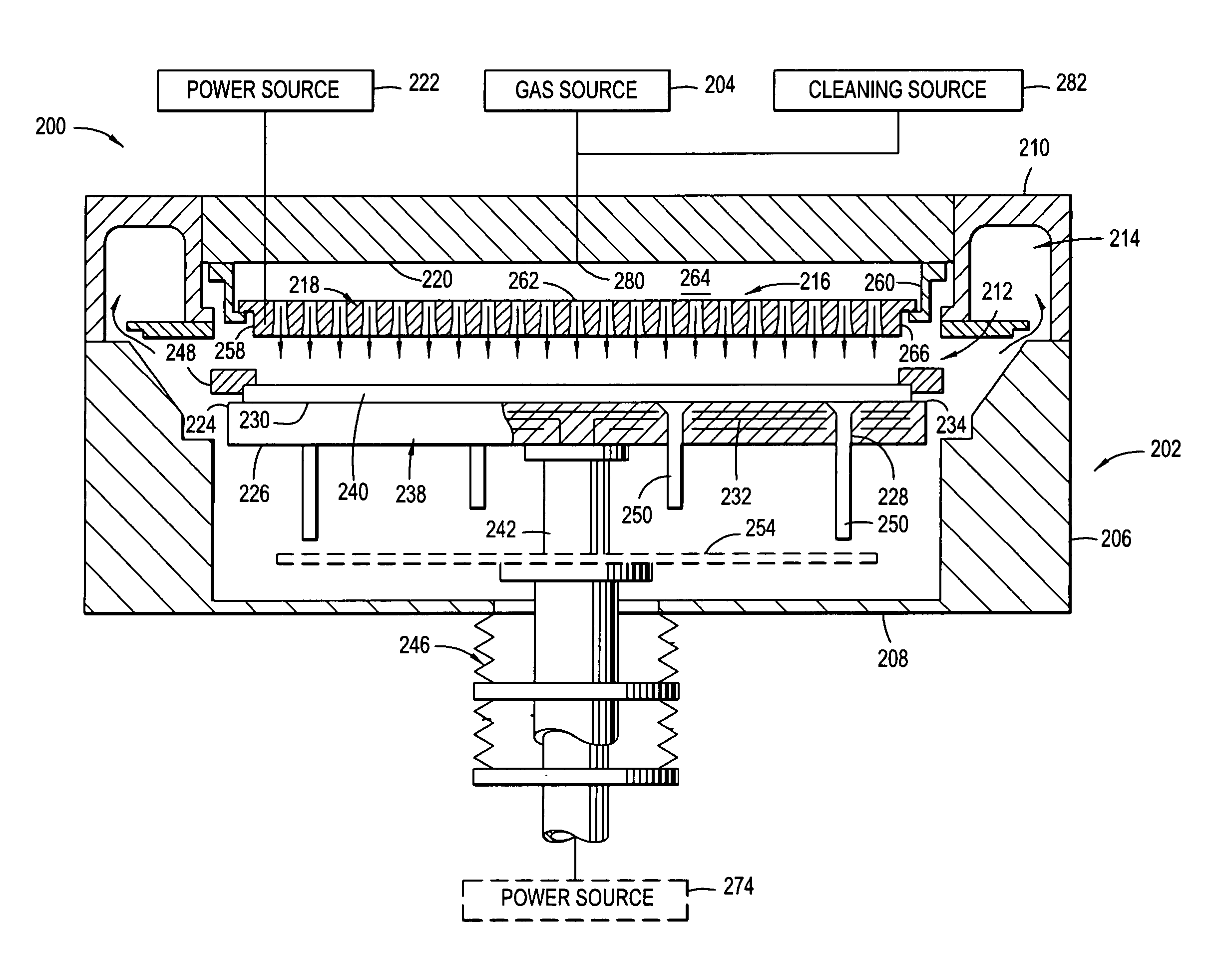
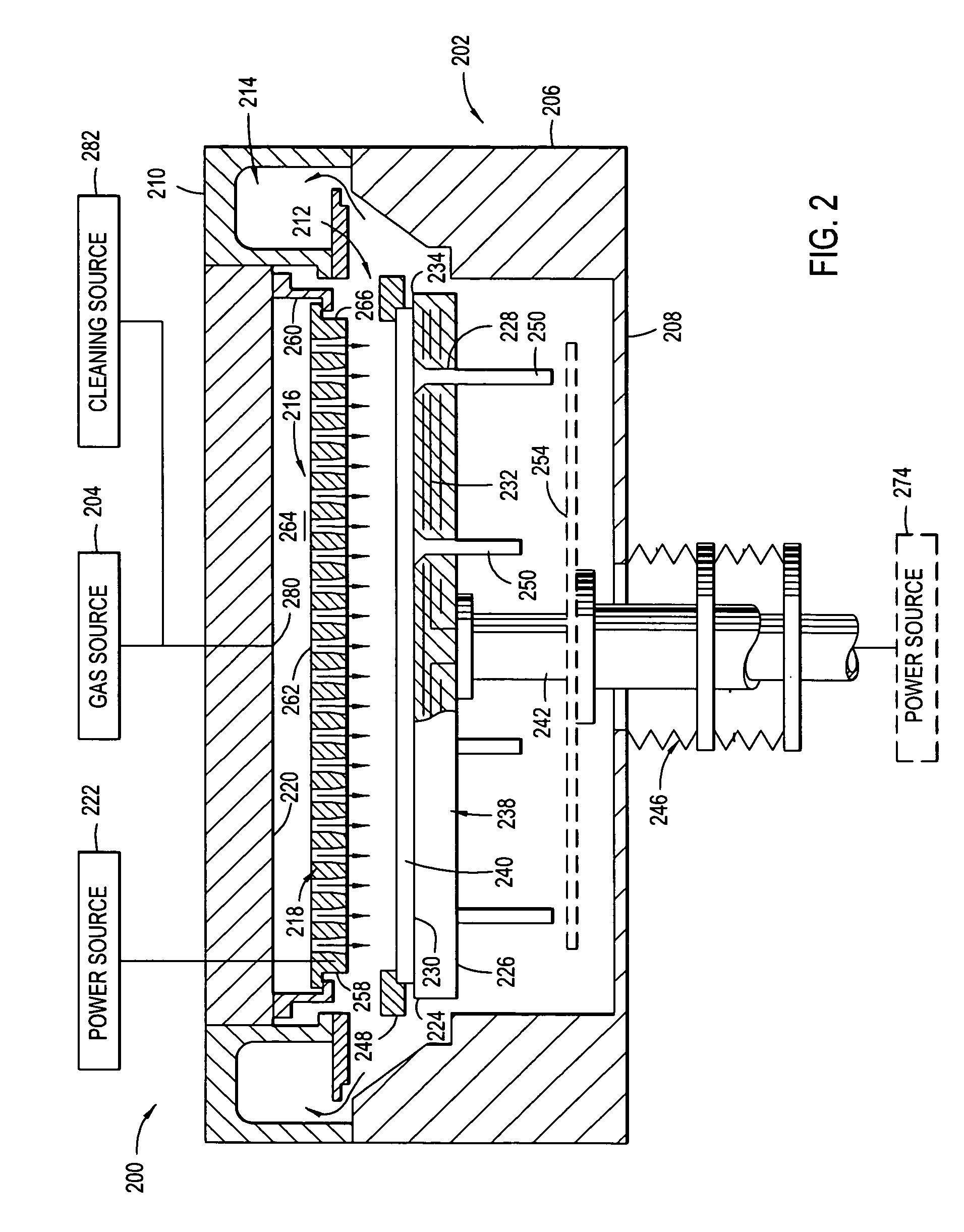
"The present invention provides a gas distribution plate assembly for a plasma processing chamber. The assembly includes a diffuser plate with an array of gas passages. The gas passages include first gas passages with a first hollow cathode cavity and a first surface area, and second gas passages with a second hollow cathode cavity and a second surface area. The first surface area is smaller than the second surface area. The invention also provides a gas distribution plate assembly with a diffuser plate having a plurality of first gas passages with a first diameter and a first depth, and a plurality of second gas passages with a second diameter and a second depth. The second diameter is larger than the first diameter or the second depth is larger than the first depth. The technical effects of the invention include improved gas distribution and more uniform plasma processing."

Problems solved by technology

As the size of substrates continues to grow in the TFT-LCD industry, film thickness and film property uniformity control for large area plasma-enhanced chemical vapor deposition (PECVD) becomes an issue.

Method used


Image

  • Plasma uniformity control by gas diffuser hole design
  • Plasma uniformity control by gas diffuser hole design
  • Plasma uniformity control by gas diffuser hole design

Examples


Embodiment Construction

[0053] The invention generally provides a gas distribution assembly for providing gas delivery within a processing chamber. The invention is illustratively described below in reference to a plasma enhanced chemical vapor deposition system configured to process large area substrates, such as a plasma enhanced chemical vapor deposition (PECVD) system, available from AKT, a division of Applied Materials, Inc., Santa Clara, Calif. However, it should be understood that the invention has utility in other system configurations such as etch systems, other chemical vapor deposition systems and any other system in which distributing gas within a process chamber is desired, including those systems configured to process round substrates.

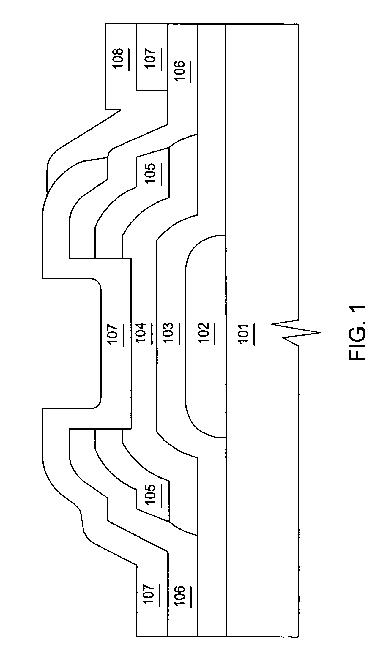
[0054]FIG. 1 illustrates cross-sectional schematic views of a thin film transistor structure. A common TFT structure is the back channel etch (BCE) inverted staggered (or bottom gate) TFT structure shown in FIG. 1. The BCE process is preferred, because the gate...


PUM

PropertyMeasurementUnit
diameteraaaaaaaaaa
depthaaaaaaaaaa
flaring angleaaaaaaaaaa

Abstract

Embodiments of a gas diffuser plate for distributing gas in a processing chamber are provided. The gas distribution plate includes a diffuser plate having an upstream side and a downstream side, and a plurality of gas passages passing between the upstream and downstream sides of the diffuser plate. The gas passages include hollow cathode cavities at the downstream side to enhance plasma ionization. The depths, the diameters, the surface area and density of hollow cathode cavities of the gas passages that extend to the downstream end can be gradually increased from the center to the edge of the diffuser plate to improve the film thickness and property uniformity across the substrate. The increasing diameters, depths and surface areas from the center to the edge of the diffuser plate can be created by bending the diffuser plate toward downstream side, followed by machining out the convex downstream side. Bending the diffuser plate can be accomplished by a thermal process or a vacuum process. The increasing diameters, depths and surface areas from the center to the edge of the diffuser plate can also be created computer numerically controlled machining. Diffuser plates with gradually increasing diameters, depths and surface areas of the hollow cathode cavities from the center to the edge of the diffuser plate have been shown to produce improved uniformities of film thickness and film properties.

Description

CROSS-REFERENCE TO OTHER APPLICATIONS [0001] This application is a continuation of co-pending U.S. patent application Ser. No. 10 / 889,683, filed Jul. 12, 2004, which claims benefit of U.S. provisional patent application Ser. No. 60 / 570,876, filed May 5, 2004. Each of the aforementioned related patent applications is herein incorporated by reference.BACKGROUND OF THE DISCLOSURE [0002] 1. Field of the Invention [0003] Embodiments of the invention generally relate to a gas distribution plate assembly and method for distributing gas in a processing chamber. [0004] 2. Description of the Background Art [0005] Liquid crystal displays or flat panels are commonly used for active matrix displays such as computer and television monitors. Plasma enhanced chemical vapor deposition (PECVD) is generally employed to deposit thin films on a substrate such as a transparent substrate for flat panel display or semiconductor wafer. PECVD is generally accomplished by introducing a precursor gas or gas mi...

Claims


Application Information

Patent Timeline
Patent Type & Authority Applications(United States)
IPC IPC(8): C23F1/00C23C16/00H01L21/02C23C16/34C23C16/44C23C16/455C23C16/505C23C16/509H01J37/32H01L21/205
CPCC23C16/345C23C16/455C23C16/45565Y10T29/49885H01J37/32082H01J37/3244Y10T29/49996C23C16/5096H01J37/32091H01J37/32541H01J37/32596H01J2237/327H01J2237/3321H01J2237/3323H01J2237/3325
Inventor CHOI, SOO YOUNGWHITE, JOHN M.WANG, QUNHUAHOU, LIKIM, KI WOONKURITA, SHINICHIWON, TAE KYUNGANWAR, SUHAILPARK, BEOM SOOTINER, ROBIN L.
Owner CHOI SOO YOUNG
Learn More