
Active-matrix display, the emitters of which are supplied by voltage-controlled current generators

a technology of active matrix display and voltage control current generator, which is applied in the direction of instruments, static indicating devices, etc., can solve the problems of introducing defects into the images displayed by the display, requiring the much more expensive use of recrystallized silicon, and diodes with an inverted structure generally have a lower efficiency and/or a shorter li

Active Publication Date: 2006-10-19
INTERDIGITAL CE PATENT HLDG
View PDF11 Cites 230 Cited by
  • Summary
  • Abstract
  • Description
  • Claims
  • Application Information

AI Technical Summary

Benefits of technology

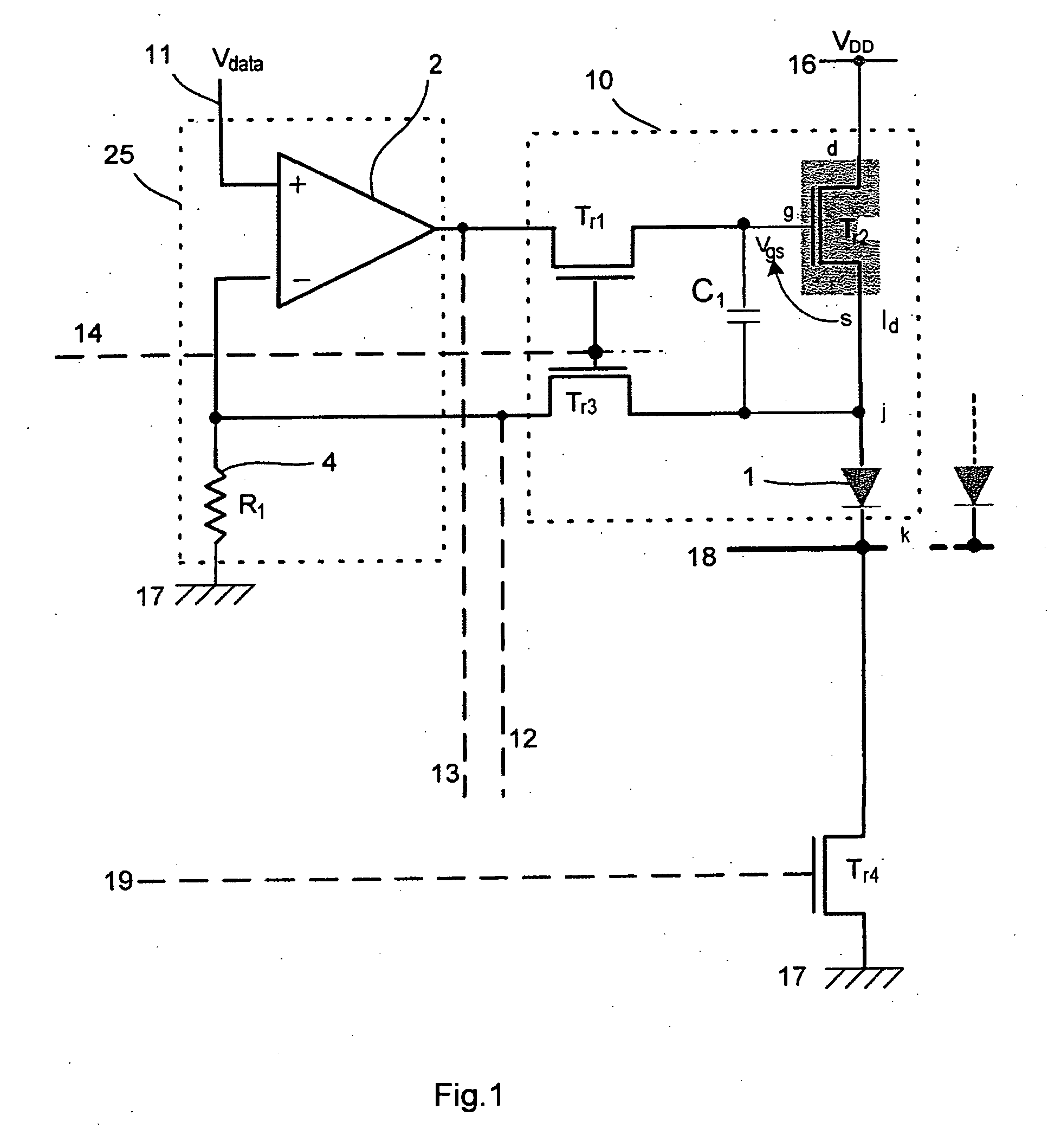
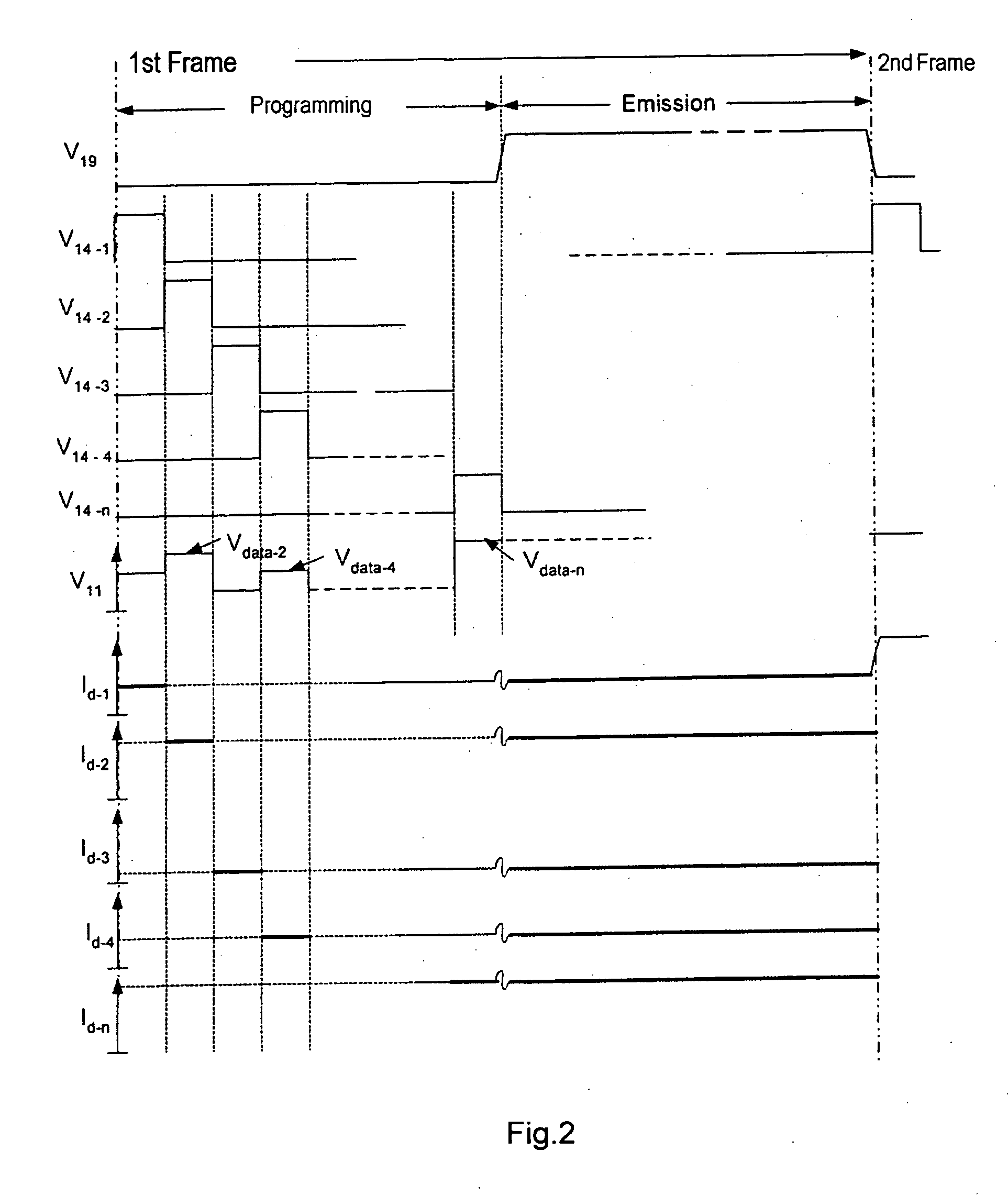
[0065] The current flowing in each emitter during this emission phase is equal to the programmed current in each pixel circuit during the programming phase and is therefore strictly proportional to the voltage representative of an image datum addressed to each pixel circuit during the programming phase. One advantage of the invention is that this current does not depend on the trip threshold voltages of the current modulation transistors of each circuit, nor on the current-voltage characteristics of the emitters, nor on any drift in these voltages and / or in these characteristics.

Problems solved by technology

Owing to the variations in the voltage Vs, the modulation and the programming of the current to be made to flow through the emitter no longer depends only on the voltage applied to the drive electrode of the modulation transistor Tr2 but also on the charge and on the ageing of the emitter, thereby introducing defects into the images displayed by the display.
However, such diodes with an inverted structure generally have a lower efficiency and / or a shorter lifetime, especially when the anode is made of a mixed indium tin oxide (ITO).
However, such a solution based on p-type transistors precludes the use of amorphous or microcrystalline silicon for the active matrix and requires the much more expensive use of recrystallized silicon.

Method used


Image

  • Active-matrix display, the emitters of which are supplied by voltage-controlled current generators
  • Active-matrix display, the emitters of which are supplied by voltage-controlled current generators
  • Active-matrix display, the emitters of which are supplied by voltage-controlled current generators

Examples


Embodiment Construction

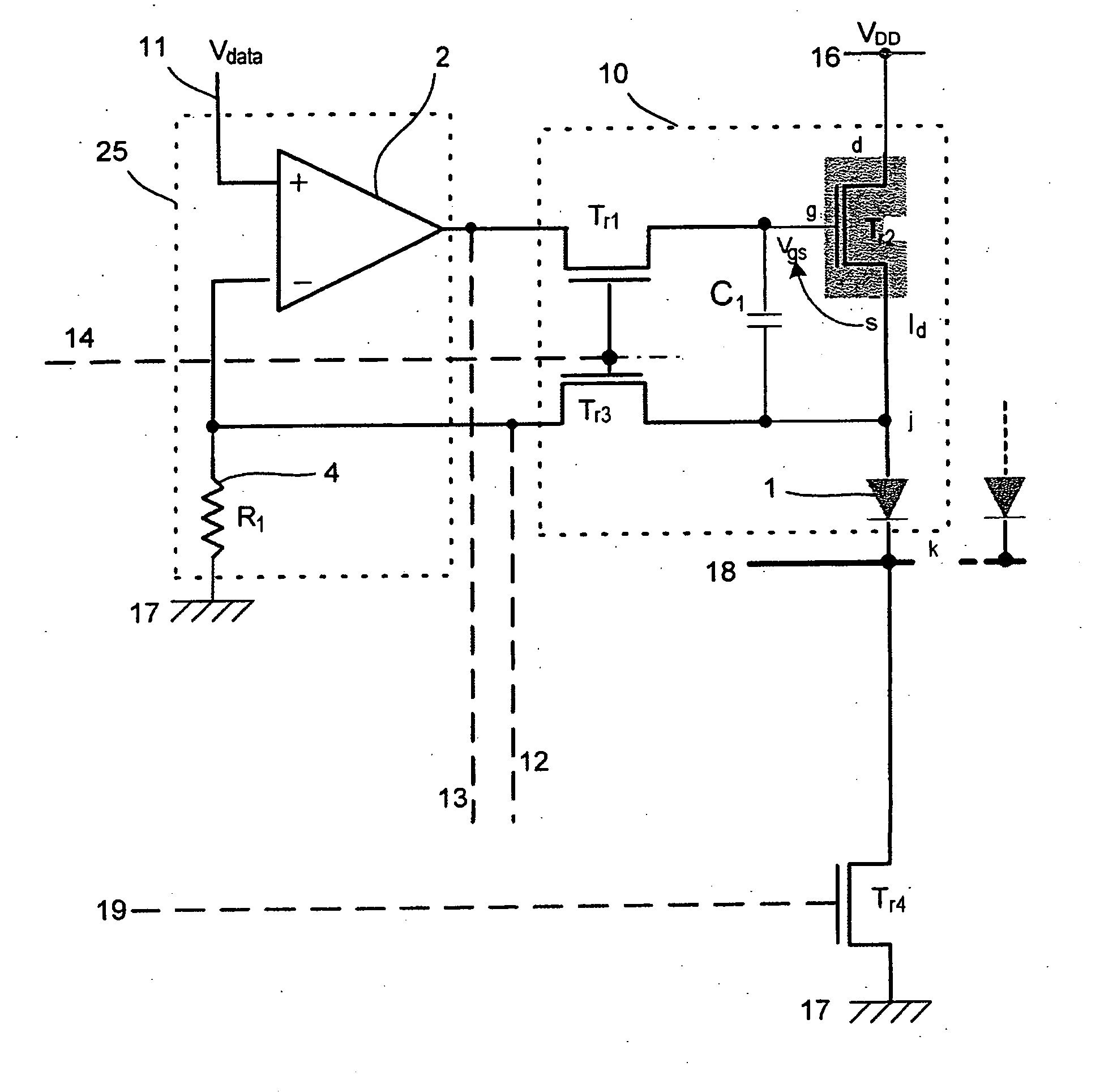
[0071] One embodiment of a display according to the invention will be described with reference to FIG. 1.

[0072] The display according to the invention comprises an array of pixel circuits 10, each including an organic light-emitting diode 1. These circuits and diodes are distributed over the display in rows and columns, these circuits being integrated into an active matrix that supports the diodes.

[0073] The display also comprises: [0074] a. supply generator (not shown) having a first output terminal at an approximately constant voltage VDD and a second output terminal connected to a ground electrode; [0075] a circuit (not shown) capable of selecting pixel circuits 10 of any one row, this circuit having, for each row of pixels, a single row select electrode 14; and [0076] a circuit 25 capable of simultaneously addressing each of the pixel circuits of any one row selected with a voltage representative of an image datum Vdata. This circuit 25 comprises, for each column of pixels, fi...


PUM


Abstract

The display comprises an array of pixel circuits each comprising an emitter 1 in series with a current modulation transistor, and at least one address circuit, which integrates, for each column, a differential amplifier and a passive element preferably a resistive element, which cooperate with the current modulation transistors so as to form, during address phases in which the emitters are switched “out of the circuit”, a voltage-programmable current generator. After the address phases, thanks to a suitable switch, the emitters are switched “into the circuit” and supplied with the preprogrammed current. Such a display allows the image display quality to be inexpensively improved.

Description

1 / FIELD OF THE INVENTION [0001] The invention relates to displays comprising an array of light emitters, especially organic light-emitting diodes, and to a method of driving these displays. 2 / DESCRIPTION OF THE PRIOR ART [0002] Document U.S. Pat. No. 6,809,706 describes, with reference to its FIG. 12A and by adopting the same references as in that document, an active-matrix display comprising an array of light emitters 1 of the current-controllable type and an array of pixel circuits 10 each comprising an emitter 1, that are distributed in rows and columns, a voltage generator VDD for supplying said emitters having first and second supply output terminals, a circuit capable of selecting pixel circuits for any one row and a circuit 25 capable of simultaneously addressing a voltage representative of an image datum to be displayed at each of the pixel circuits of any one row selected, where each pixel circuit 10 includes, in addition to the emitter 1 that can be supplied between first ...

Claims


Application Information

Patent Timeline
IPC IPC(8): G09G3/30
CPCG09G3/30G09G3/3233G09G2300/0842G09G2300/043G09G2300/0809G09G3/3291G09G3/20
Inventor ROY, PHILIPPE LEPRAT, CHRISTOPHEMARTIN, PIERRICK
Owner INTERDIGITAL CE PATENT HLDG
Learn More