
Clutch disc assembly with direct bond ceramic friction material

a technology of friction material and clutch disc, which is applied in the direction of friction lining, interlocking clutch, coupling, etc., can solve the problems of ceramic material wearing the engagement surface, organic materials wear faster than ceramic materials, etc., and achieve the effect of easy switching between ceramic materials

Inactive Publication Date: 2006-10-19
EATON CORP
View PDF16 Cites 21 Cited by
  • Summary
  • Abstract
  • Description
  • Claims
  • Application Information

AI Technical Summary

Benefits of technology

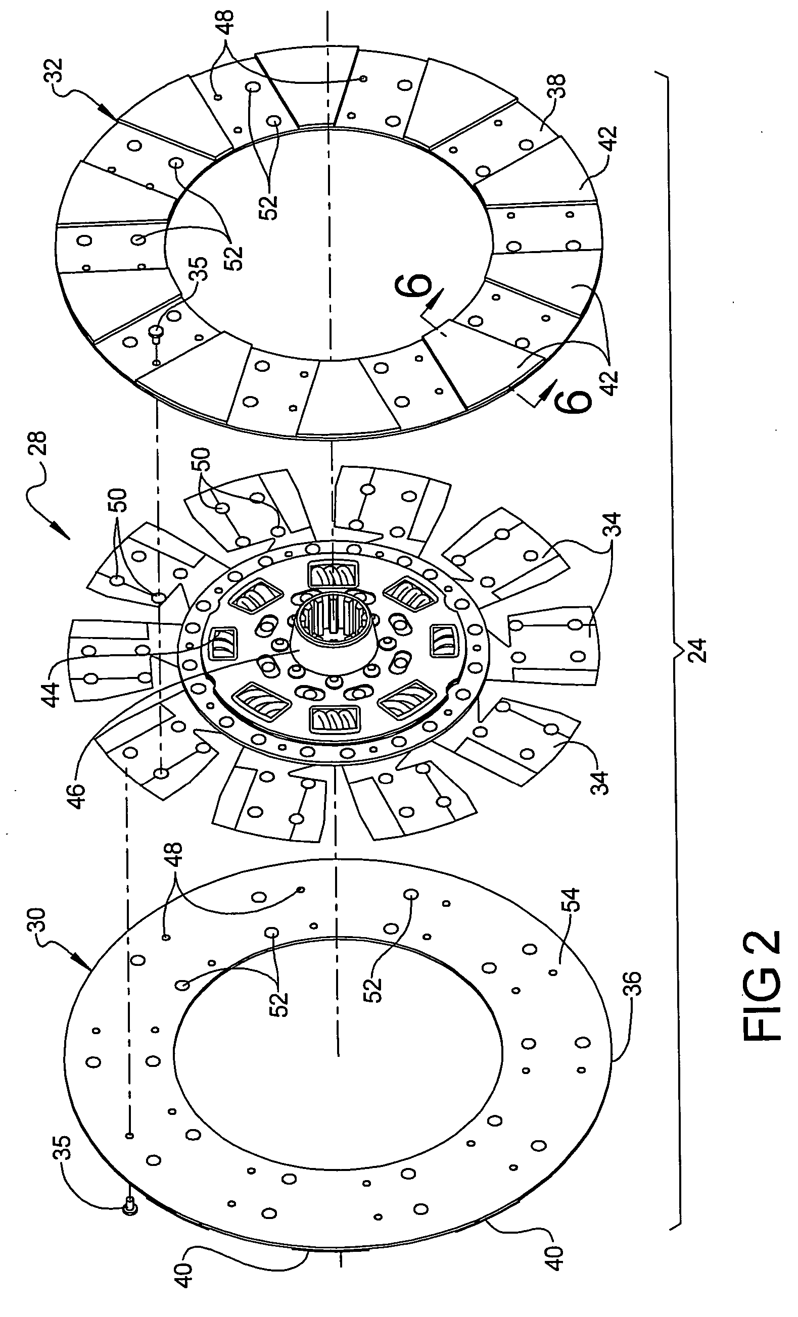
[0004] The present invention provides a lower clutch inertia disc employing ceramic friction material. The present invention also provides a clutch disc assembly in which it is possible to easily switch between ceramic and organic material. The present invention also provides a clutch which has approximately the same axial thickness as an organic material clutch disc assembly. The present invention also provides a clutch disc assembly having some or all of the benefits of both ceramic clutch disc assemblies and organic clutch disc assemblies. The present invention also provides a clutch disc assembly that has the wear characteristics of organic on a clutch flywheel.

Problems solved by technology

Organic materials wear faster than ceramic materials.
However, ceramic materials wear the engagement surfaces of the engaging plate element, commonly a machined cast iron surface, faster than organic materials.

Method used


Image

  • Clutch disc assembly with direct bond ceramic friction material
  • Clutch disc assembly with direct bond ceramic friction material
  • Clutch disc assembly with direct bond ceramic friction material

Examples


Embodiment Construction

[0016] Certain terminology will be used in the following description for convenience in reference only and will not be limiting. For example, the terms “forward” and “rearward” will refer to directions forward and rearward of a transmission as normally mounted in a vehicle. The terms “rightward” and “leftward” will refer to directions in the drawings in connection with which the terminology is used. The terms “inwardly” and “outwardly” will refer to directions toward and away from, respectively, the geometric center of the apparatus. The terms “upward” and “downward” will refer to directions as taken in the drawings in connection with which the terminology is used. All foregoing terms mentioned above include the normal derivatives and equivalents thereof.

[0017] Referring to FIG. 1 of the drawings, a partial cross-sectional view of a clutch / transmission assembly 10 is shown. An engine flywheel 12 is rotatably coupled to a clutch cover 14. A gear change transmission 16 is nonrotatabl...


PUM


Abstract

A clutch disc assembly for a friction torque device has a clutch damper assembly which includes a hub defining an axis of rotation. The damper assembly includes a plurality of cushion elements extending radially outwardly away from the axis of rotation. A first friction ring includes a backer plate fixed to the cushion elements by circumferentially distributed rivets. At least one ceramic friction element is bonded to the backer plate.

Description

RELATED APPLICATIONS [0001] This application claims the benefit of U.S. Provisional Application No. 60 / 671,854, filed Apr. 15, 2005 entitled “Clutch Disc Assembly With Direct Bond Ceramic Friction Material”, which is incorporated herein by reference in its entirety.FIELD OF THE INVENTION [0002] The present invention relates to clutch disc assemblies. More specifically, the present invention relates to the mounting of friction materials on clutch disc assemblies and to the arrangement of friction material on a clutch disc assembly. BACKGROUND OF THE INVENTION [0003] Motor vehicle clutch driven disc assemblies, or simply clutch disc assemblies, typically employ two types of friction materials—ceramic and / or organic. Organic friction materials are inherently softer than ceramic materials, deflecting more on engagement. This makes it easier to engage a clutch with organic material than with ceramic material without undesired harshness and without stalling the vehicle's engine. Organic m...

Claims


Application Information

Patent Timeline
IPC IPC(8): F16D13/64F16D69/02F16D69/04
CPCF16D13/38F16D13/64F16D2200/0043F16D2013/642F16D69/027
Inventor BASSETT, MICHAEL L.RYNEARSON, STEVEN J. JR.
Owner EATON CORP
Learn More