
Synchronization in a distributed system

Inactive Publication Date: 2006-10-12
PALO ALTO RES CENT INC
View PDF86 Cites 67 Cited by
  • Summary
  • Abstract
  • Description
  • Claims
  • Application Information

AI Technical Summary

Benefits of technology

[0016] A method for synchronizing control efforts of a plurality of controllers can include receiving updated process information in association with a time stamp indicating when the updated process information was collected, determining a maximum delay associated with distributing the updated process information to at least one of the plu

Problems solved by technology

The network or communications scheme may be associated with communication delays.
Synchronizing controllers or processes in the face of such delays can be problematic.
However, as system size increases, the computational capabilities of a single platform can be overwhelmed.
Additionally, providing individual interfaces between the single computational platform and each of the sensors and actuators of the system can be impractical.
Furthermore, where it is desirable to assemble or reconfigure a system from various subcomponents, the direct interfacing of sensors and actuators to the central platform becomes problematic.
However, this may limit the scalability of the system.
For example, as the size of the system increases, the capabilities and / or resources of the main control coordinator (or processor running the main control coordinator) may be overwhelmed.
However, as machines become more complex and contain larger numbers of embedded processors, instances of tightly coupled distributed control systems are becoming more common.
However, these documents do not appear to discuss the coordination or synchronization of the use of feedback or updated process information.
However, the phase selecting technique of Mushkin is not applicable to the more complex synchronizations required in and between control processes.

Method used


Image

  • Synchronization in a distributed system
  • Synchronization in a distributed system
  • Synchronization in a distributed system

Examples


Embodiment Construction

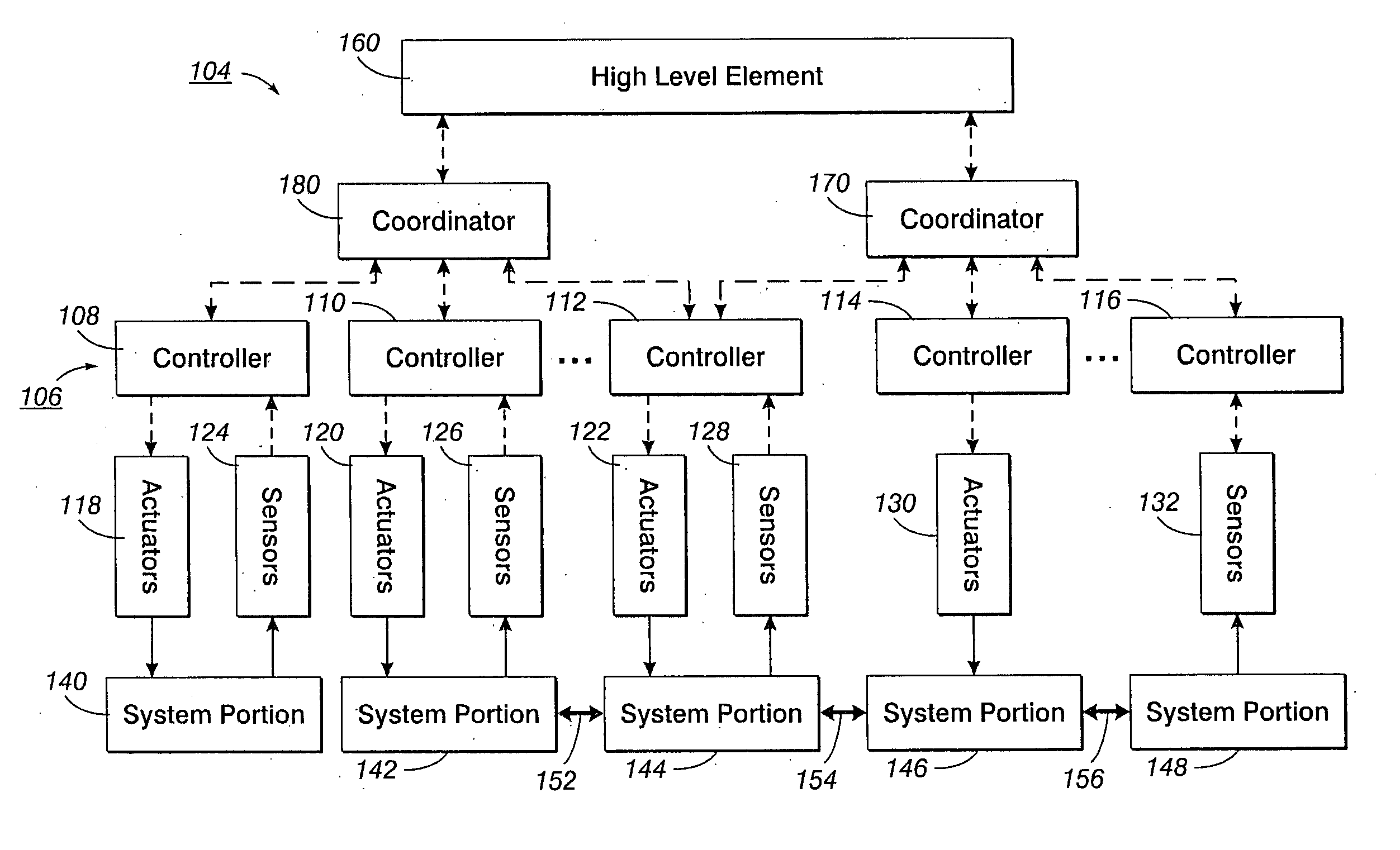
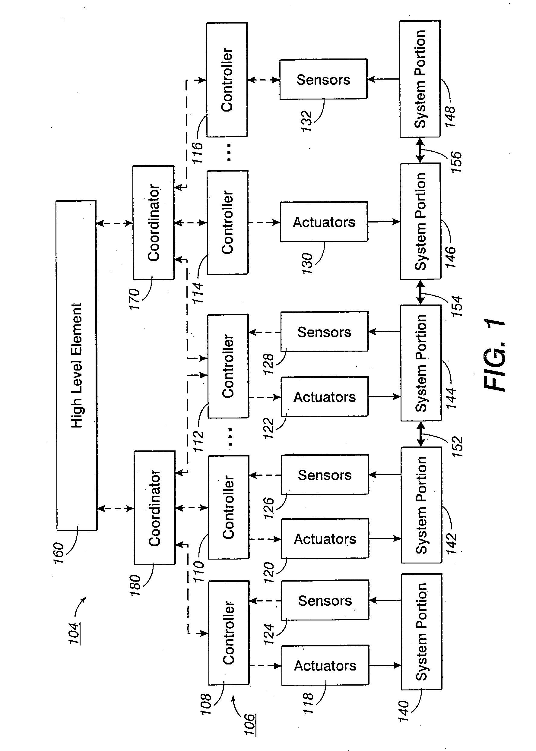
[0040] Referring to FIG. 1, distributed systems (e.g., 104) often include a communications network for carrying communication between system elements (e.g., 108, 110, 112, 114, 116, 118, 120, 122, 124, 126, 128, 130, 132, 160, 170, 180). Communication in such networks is subject to communication delays. The delays can be significant when compared to system update periods, especially where systems are tightly coupled and system elements need to behave in a cooperative manner. In such systems, some mechanism is needed to ensure that the efforts of one controller or process are synchronized to the efforts of another system element or controller.

[0041] One method for ensuring cooperative control efforts is for each cooperating element to be constantly updated as to the activities of the other cooperating elements, and / or as to the status of progress of a task or workpiece. However, such methods require a great deal of inter-element communication, which may over-burden a system network ...


PUM


Abstract

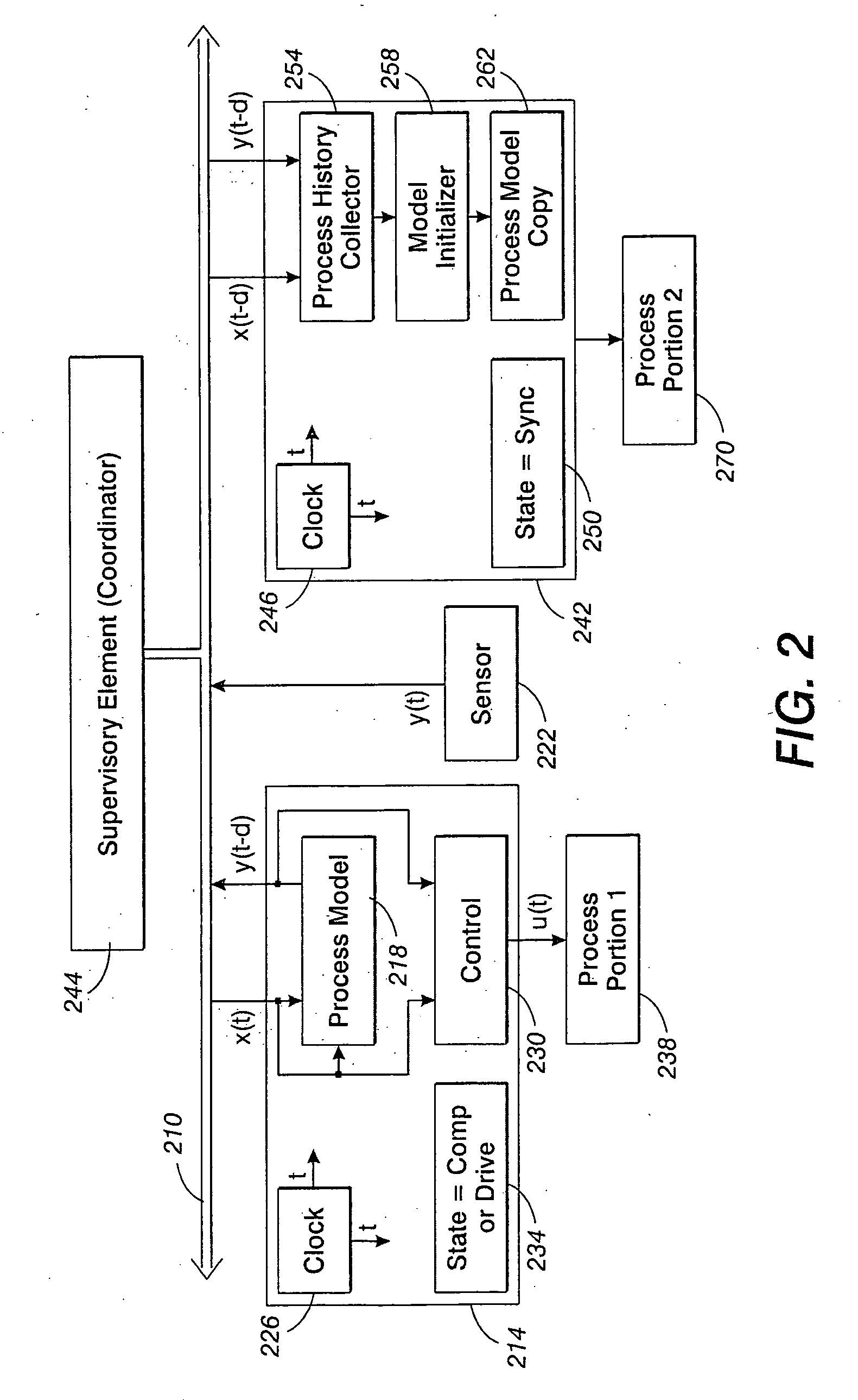
A method for synchronizing the control efforts of a plurality of controllers includes determining an apply time for using updated information. The apply time can take into account worst case processing and / or communication delays across a system. Reacting to the updated information only after at the apply time ensures that all system elements are able to react to the updated information in concert. A time stamp indicates when the data was collected. The apply time indicates when the data can be used. Process modeling or simulation is used to estimate system status at the apply time based on the system status at the time of the time stamp, the updated information, and predetermined information regarding the behavior of the system over time. In a document processor, the method allows tightly coupled modules, such as sheet transportation modules, to behave in a cooperative manner when separate modules are in contact with the same sheet.

Description

CROSS REFERENCE [0001] The following applications, the disclosures of each being totally incorporated herein by reference are mentioned: U.S. patent application, filed, for Coordination in a Distributed System by Lara S. Crawford, et al. (20041210-US-NP, XERZ 2 00863); U.S. patent application Ser. No., filed, for On-The-Fly State Synchronization in a Distributed System by Haitham A. Hindi et al. (20041214-US-NP, XERZ 2 00865); and U.S. patent application Ser. No., filed, for Communication in a Distributed System by Markus P. J. Fromherz et al. (20041213-US-NP, XERZ 2 00864). BACKGROUND [0002] There is illustrated herein in embodiments, an architecture including methods and systems for synchronizing between elements in a distributed system. For example, a distributed system may include a collection of modules, each with its own function. The collection of modules may be interconnected to carry out a particular function or functions. The interconnection may be physical and / or logical ...

Claims


Application Information

Patent Timeline
IPC IPC(8): G06K15/00
CPCG05B19/4185G05B2219/45187G05B2219/31213Y02P90/02
Inventor CRAWFORD, LARA S.HINDI, HAITHAM A.
Owner PALO ALTO RES CENT INC
Learn More