
Brake spider and axle housing assembly

a technology of axle housing and axle, which is applied in the direction of wheel manufacturing, mechanical equipment, transportation and packaging, etc., can solve the problems of adversely affecting the seal and bearing assembly, premature wear and damage of various wheel end components, and time-consuming and expensive, so as to reduce the potential for premature wear or damage of other wheel end components, the effect of cost and labor reduction

Inactive Publication Date: 2006-10-12
ARVINMERITOR TECH
View PDF5 Cites 12 Cited by
  • Summary
  • Abstract
  • Description
  • Claims
  • Application Information

AI Technical Summary

Benefits of technology

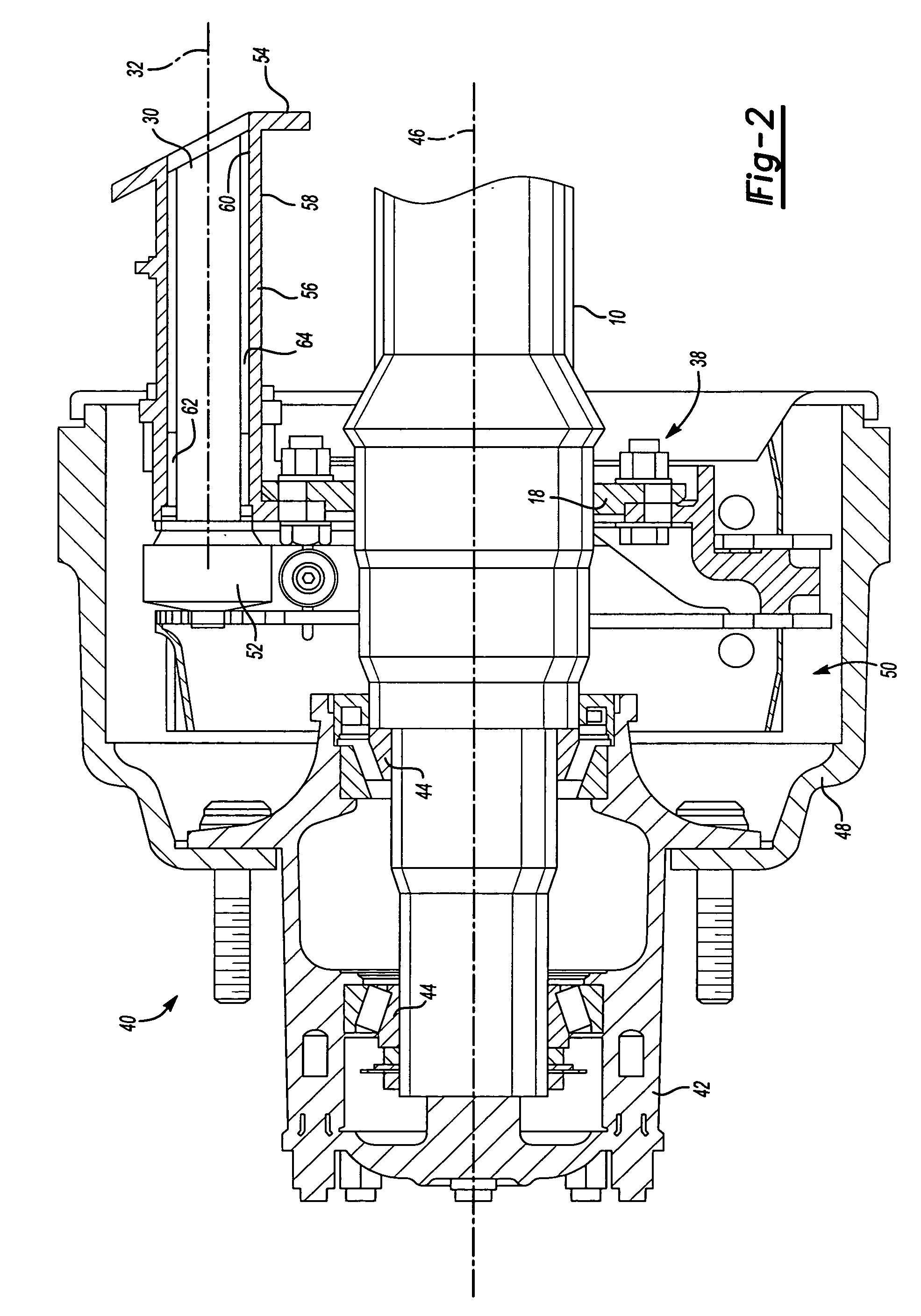
[0008] A brake spider includes a spider body having a central opening that surrounds an axle housing. A slot is formed within the spider body to receive a camshaft and a camshaft bracket assembly. The slot is defined by a surface that does not completely surround the camshaft. The slot allows the camshaft to be removed from a wheel end without requiring removal of other wheel end components.
[0009] In one example, a wheel hub is mounted for rotation relative to the axle housing about a wheel axis of rotation. A brake drum is mounted for rotation with the wheel hub about the wheel axis of rotation. The brake drum defines a cavity in which the brake spider is mounted. The camshaft rotates about a camshaft axis of rotation to actuate a brake component, such as brake shoes for example, in response to a braking command. By positioning the camshaft and the camshaft bracket assembly within the slot of the brake spider, the camshaft and the camshaft bracket assembly can be removed for service as needed without having to remove the wheel hub.
[0011] The subject invention provides a simplified method and apparatus for removing a camshaft from a wheel end assembly that does not require a wheel hub to be removed. This reduces cost and labor, as well as reducing the potential for premature wear or damage to other wheel end components. These and other features of the present invention can be best understood from the following specification and drawings, the following of which is a brief description.

Problems solved by technology

This is time consuming and expensive.
Additionally, removing the wheel hub from the vehicle axle can adversely affect seal and bearing assemblies.
This can lead to premature wear for various wheel end components.

Method used


Image

  • Brake spider and axle housing assembly
  • Brake spider and axle housing assembly
  • Brake spider and axle housing assembly

Examples


Embodiment Construction

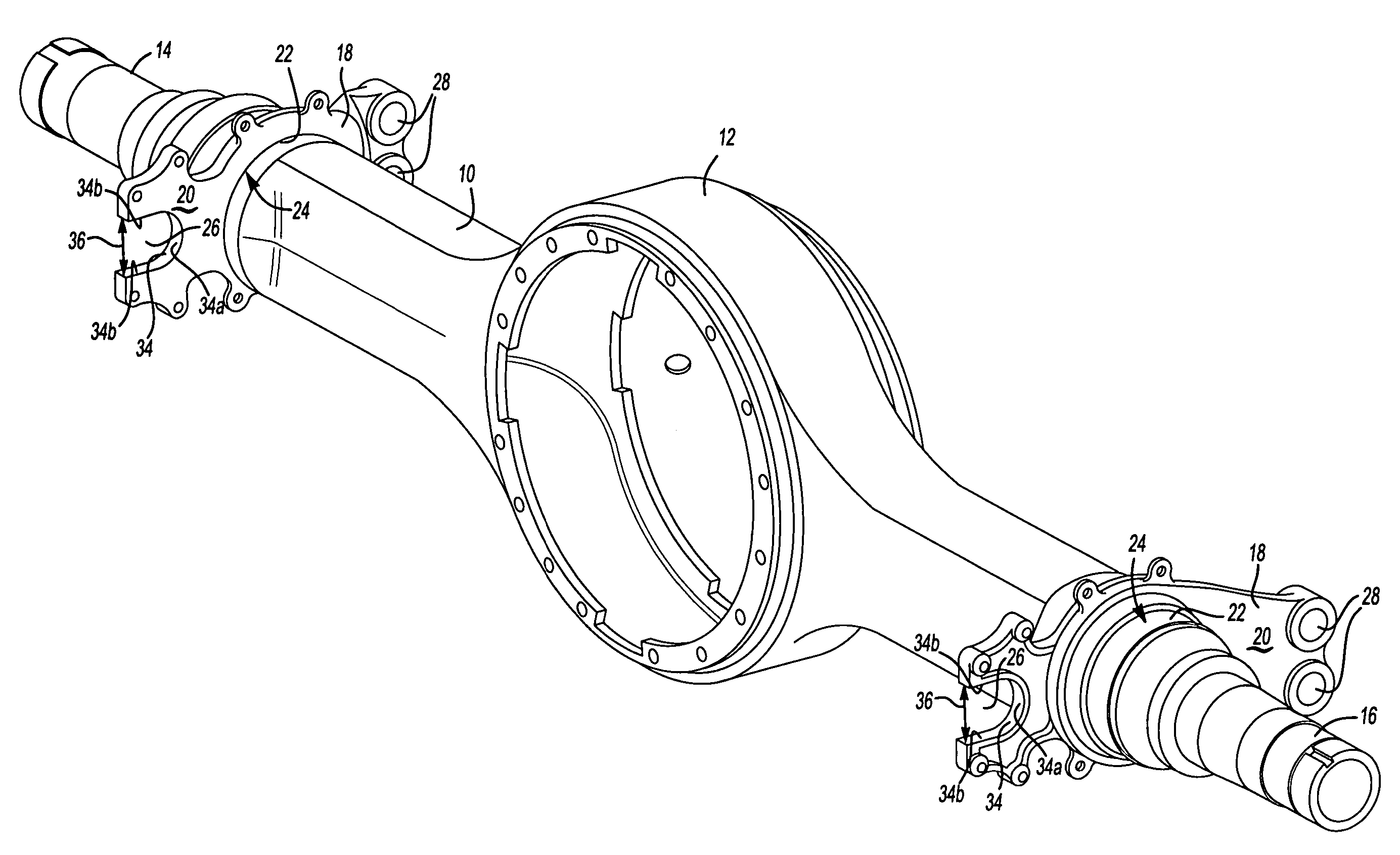
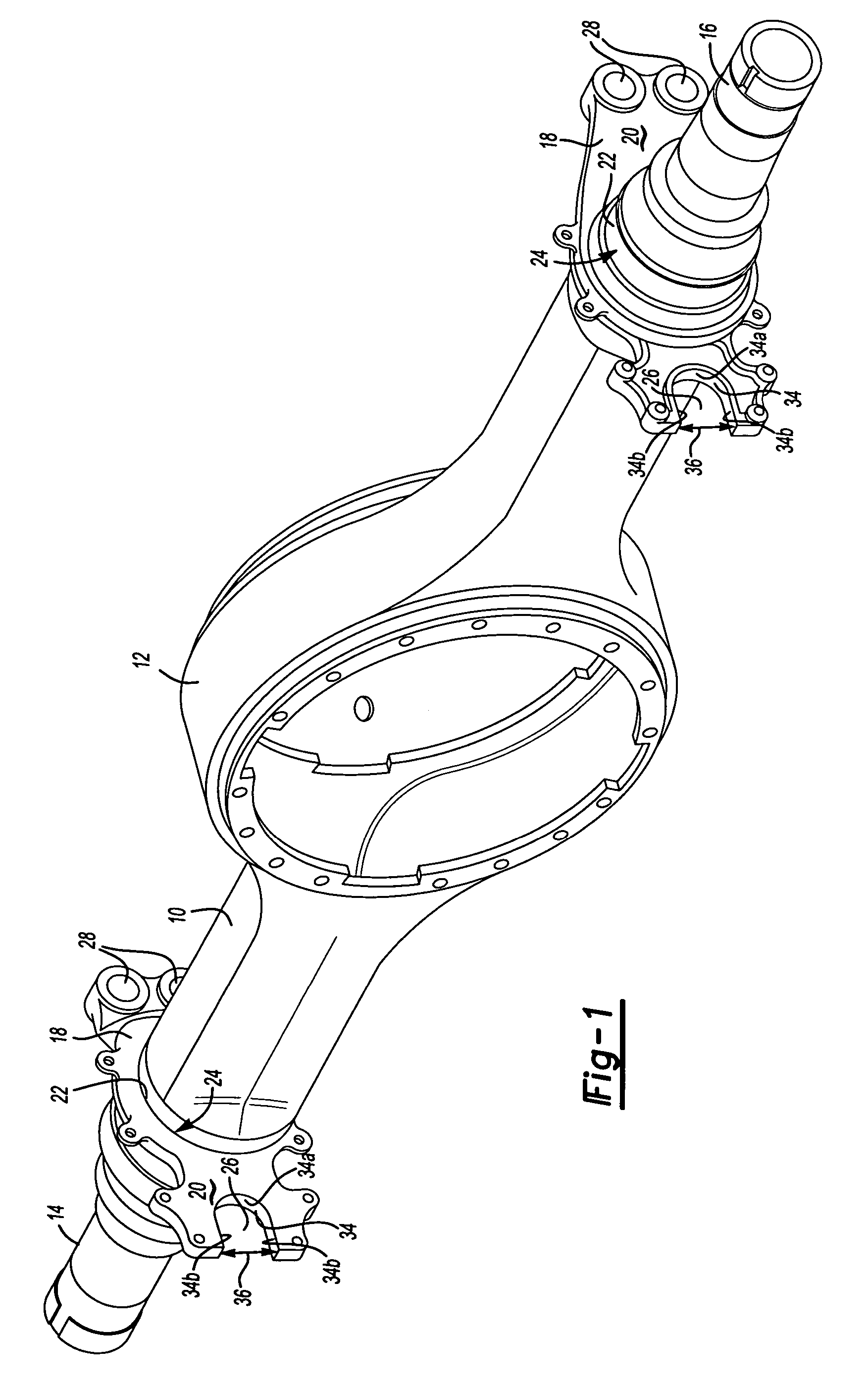
[0015] An axle housing 10 is shown in FIG. 1. The axle housing 10 includes a center portion 12 that is positioned between first 14 and second 16 axle ends. A unique brake spider 18 is mounted to each of the first 14 and second 16 axle ends or is mounted to leg portions of the axle housing 10. The brake spider 18 is preferably attached by welding, however, other attachment methods could also be used.

[0016] The brake spider 18 is configured to provide advantages for assembling and disassembling components to and from the axle housing 10 when compared to prior spider configurations. In the example shown, the axle housing 10 comprises a drive axle housing, however, it should be understood that any type of axle could utilize the brake spider 18.

[0017] The brake spider 18 includes a spider body 20 with a center opening 22. The center opening 22 surrounds the axle housing 10. Preferably, the spider body 20 is welded at 24 (see FIG. 3) to the axle housing 10 about the center opening 22. T...


PUM


Abstract

A brake spider includes a spider body with a central opening and a slot for receiving a camshaft and bracket assembly. The brake spider is attached to an axle housing via the central opening. The slot is defined by an inner surface that does not completely surround the camshaft. The slot allows the camshaft and bracket assembly to be removed from a wheel end assembly for service operations without having to remove other components from the wheel end assembly, such as a wheel hub, for example.

Description

TECHNICAL FIELD [0001] The subject invention relates to a wheel end and axle assembly having an integrated brake spider where a camshaft and bracket assembly is removable from the wheel end and axle assembly without requiring removal of a wheel hub. BACKGROUND OF THE INVENTION [0002] Wheel end assemblies are supported on opposing ends of a vehicle axle. The vehicle axle includes an axle housing that extends between the wheel end assemblies. Each wheel end assembly includes a brake assembly and a wheel hub supported on bearings for rotation relative to the axle housing. The brake assembly includes a brake drum that is mounted for rotation with the wheel hub and a brake spider that mounts non-rotating brake components to the axle housing. [0003] Non-rotating brake components include brake shoes that are pivotally supported by anchor pins at one shoe end, and which are actuated by a camshaft at an opposite shoe end. The camshaft rotates to move the brake shoes into engagement with the ...

Claims


Application Information

Patent Timeline
Patent Type & Authority Applications(United States)
IPC IPC(8): F16D65/14
CPCB60B35/121B60B35/16B60B35/18B60B2310/302F16D2125/28B60B2900/113F16D65/22F16D2051/003B60B2380/14
Inventor INADA, JORGEMALKOWSKI, JOSEPH L.KAY, JOSEPH A.HAYFORD, ROY LEECORY, THOMAS M.
Owner ARVINMERITOR TECH
Learn More