
Decompressor and vehicle

a decompressor and vehicle technology, applied in mechanical equipment, machines/engines, valve arrangements, etc., can solve the problems of significant increase in the pressure of lubricating oil, extremely high viscosity of lubricating oil, etc., to reduce friction between the decompressor pin operating shaft and the decompressor pin. , the effect of compact structur

Active Publication Date: 2006-10-12
YAMAHA MOTOR CO LTD
View PDF7 Cites 14 Cited by
  • Summary
  • Abstract
  • Description
  • Claims
  • Application Information

AI Technical Summary

Benefits of technology

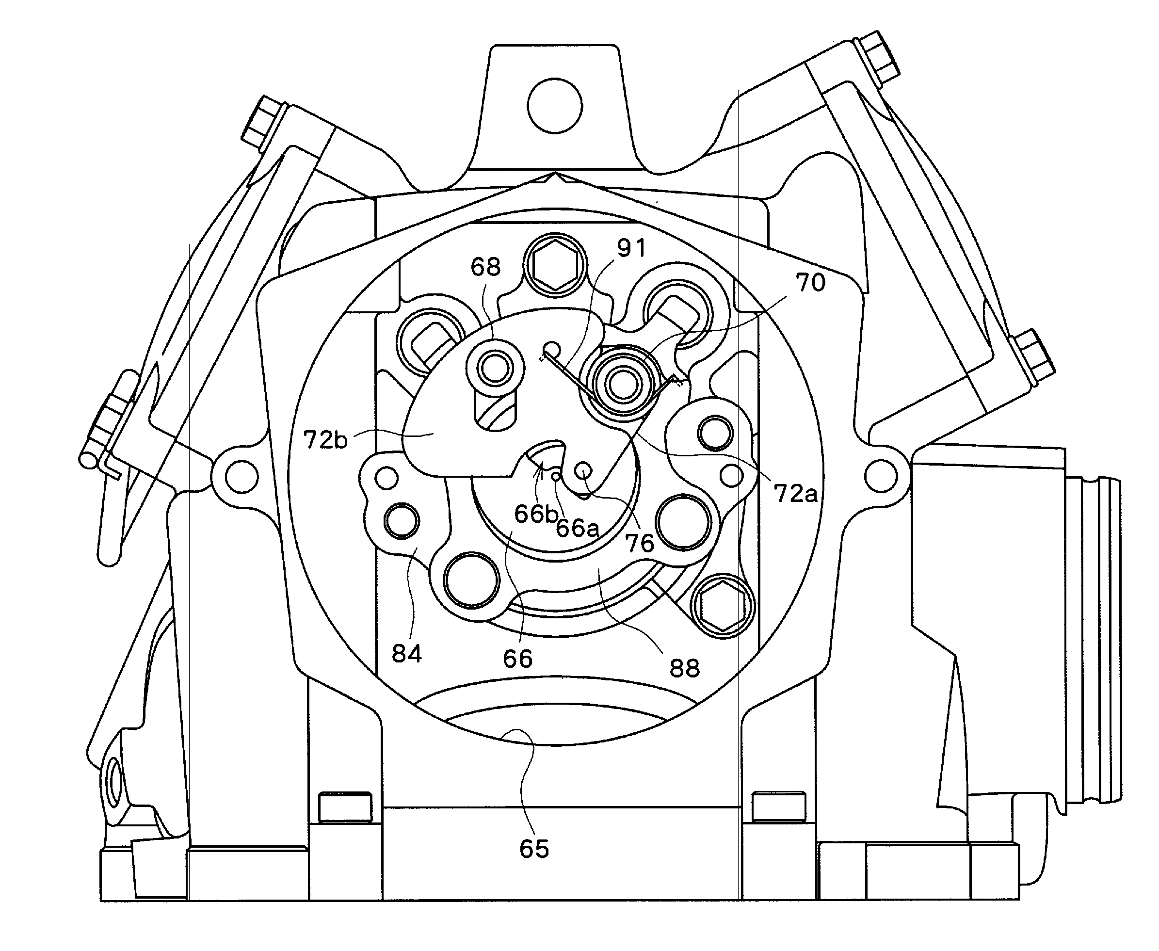
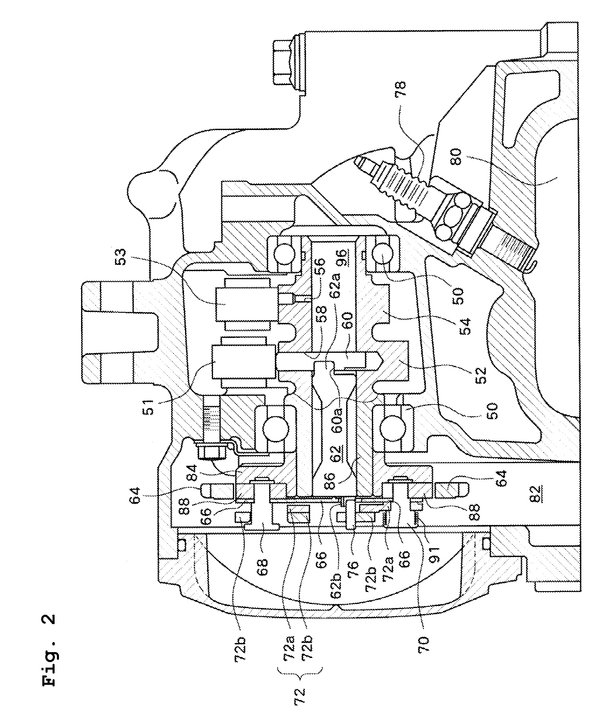
[0009] According to the present preferred embodiment, a restricting member separate from the fly weight is provided to limit the axial movement of the decompressor pin operating shaft. Accordingly, even if the pressure of the lubricating oil increases, the decompressor mechanism can be operated normally.
[0010] According to another preferred embodiment of the invention, the restricting member is disposed between the fly weight and the decompressor pin operating shaft, and prevents the end surface of the decompressor pin operating shaft from coming into contact with the fly weight. This structure can reliably prevent the decompressor pin operating shaft from pushing the fly weight and locking the motion of the fly weight.
[0011] According to another preferred embodiment of the present invention, the restricting member is a plate that is in contact with one end of the decompressor pin operating shaft. This provides a decompressor mechanism that can operate normally even if the pressure of the lubricating oil increases with a compact structure that is easy to manufacture and mount.
[0012] In this case, the restricting member may have a projection that is in contact with the axial center of the decompressor pin operating shaft at the end of the decompressor pin operating shaft. This structure can reduce the friction between the decompressor pin operating shaft and the restricting member.
[0013] According to another preferred embodiment of the present invention, the fly weight is separate from a sprocket for rotating the valve cam shaft, and the sprocket is mountable to the decompressor pin operating shaft after the fly weight is mounted to the valve cam shaft. Thus, the decompressor mechanism can be assembled independently from the assembly of the cam chain and the sprocket. This can prevent assembly problems and improve productivity.
[0014] A vehicle according to another preferred embodiment of the present invention includes one of the above described decompressors. This can provide vehicles with a reliable decompressor mechanism. The vehicles may preferably include saddle-type vehicles and compact four wheel vehicles. The saddle-type vehicles include motor-bicycles (including motorbikes and motor scooters), four wheel buggies (all terrain vehicles), and snowmobiles. The compact four wheel vehicles include two seater or four seater four wheel buggies (all terrain vehicles).

Problems solved by technology

However, under very low temperatures, the viscosity of lubricating oil becomes extremely high, and the pressure of the lubricating oil significantly increases.

Method used


Image

  • Decompressor and vehicle
  • Decompressor and vehicle
  • Decompressor and vehicle

Examples


Embodiment Construction

[0025] The present invention is described in detail below based on preferred embodiments, with reference to the attached drawings.

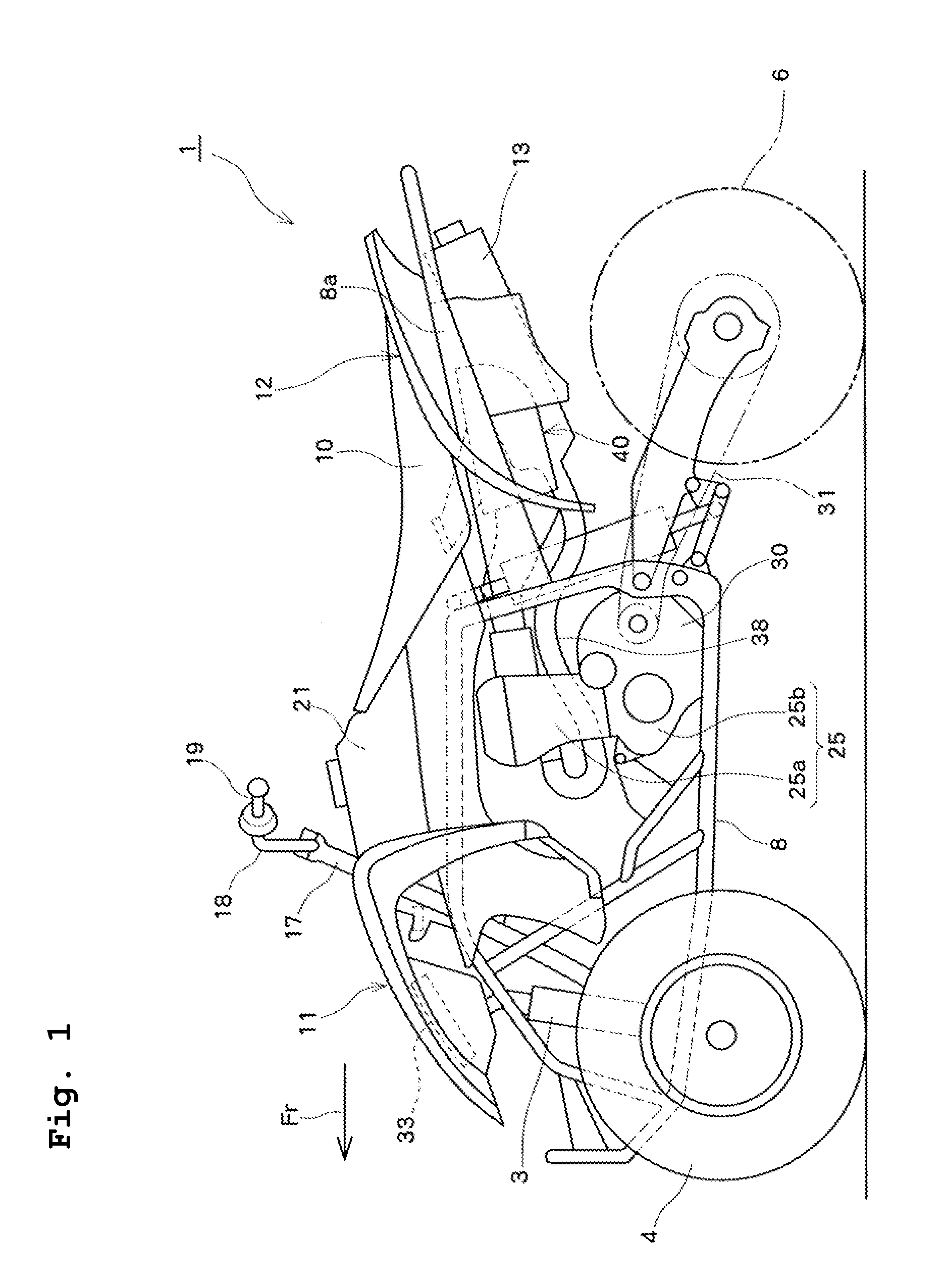
[0026]FIG. 1 is a side view of a saddle-type vehicle (all terrain vehicle) according to a preferred embodiment of the present invention. As shown in the drawing, a vehicle 1 has front suspensions 3 and 3 on the right and left of the vehicle at the front in the direction of travel (indicated by arrow Fr in the drawing), and front wheels 4 and 4 journaled at the lower ends. Front fenders 11 and 11 are disposed above the front wheels 4 and 4. The upper ends of the front suspensions 3 and 3 are supported by a body frame 8. The front end of the body frame 8 in the traveling direction journals a steering shaft 17 such that the front end can be turned to the right and left. At the upper end of the steering shaft 17, a handle 18 extending to the right and left is supported at the center thereof. Grips 19 and 19 are provided on both ends of the handle 18. The rig...


PUM


Abstract

An engine decompressor includes a decompressor pin provided through a pin hole on the surface of a valve cam, a decompressor pin operating shaft in an oil passage provided in a valve cam shaft of the valve cam for vertically moving the decompressor pin by its rotation, a fly weight rotatable by rotation of the valve cam shaft so as to rotate the decompressor pin operating shaft, and a thrust receiving plate separate from the fly weight for restricting the axial movement of the decompressor pin operating shaft in the oil passage. The engine decompressor is capable of operating a decompressor mechanism normally even if the lubricating oil increases in pressure.

Description

BACKGROUND OF THE INVENTION [0001] 1. Field of the Invention [0002] The present invention relates to a decompressor and a vehicle, and in particular, it relates to an improvement in a decompressor of the type having a decompressor pin operating shaft in an oil passage provided in a valve cam shaft. [0003] 2. Description of the Related Art [0004] Decompressors of engines force exhaust valves to open slightly in the process of compression at engine start-up or at engine stopping, thereby reducing the cranking torque of the engine to improve engine start-up performance. In other words, the decompressor releases a portion of compressed gas from a combustion chamber by slightly opening exhaust valves in the process of compression, thereby reducing cranking torque. Also, the decompressor slightly opens exhaust valves to reduce cranking torque during engine starting. The provision of such a decompressor to an engine allows an engine starter motor to be decreased in size and a battery for d...

Claims


Application Information

Patent Timeline
IPC IPC(8): F01L13/08
CPCF01L13/08
Inventor ASANO, YUUICHIHIRUKAWA, ITSUSHIOKAMOTO, YASUHIRO
Owner YAMAHA MOTOR CO LTD
Learn More