
System, method and apparatus for acoustic fluid flow measurement

Inactive Publication Date: 2006-10-12
ADVANCED FLOW TECH
View PDF25 Cites 39 Cited by
  • Summary
  • Abstract
  • Description
  • Claims
  • Application Information

AI Technical Summary

Benefits of technology

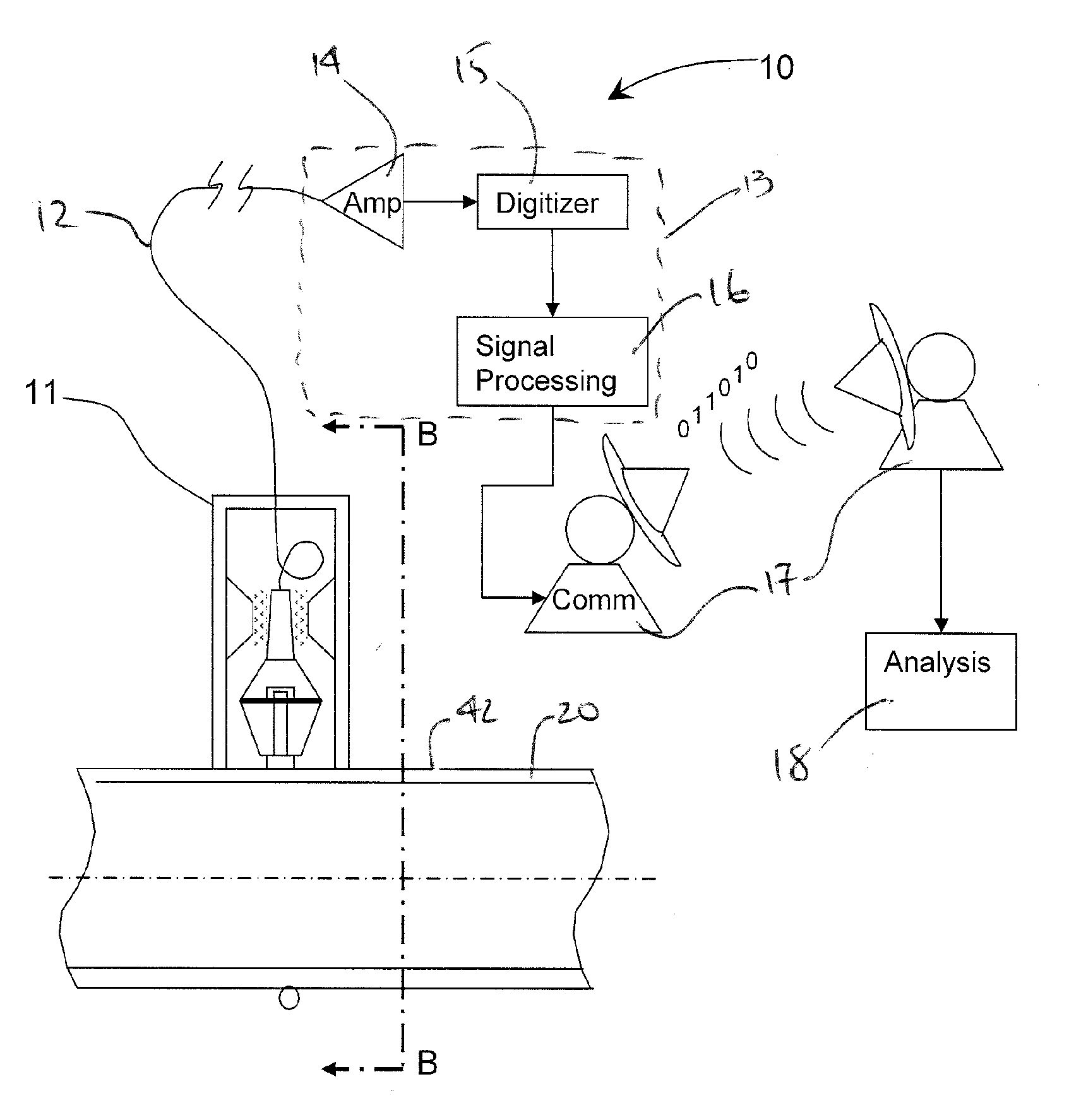
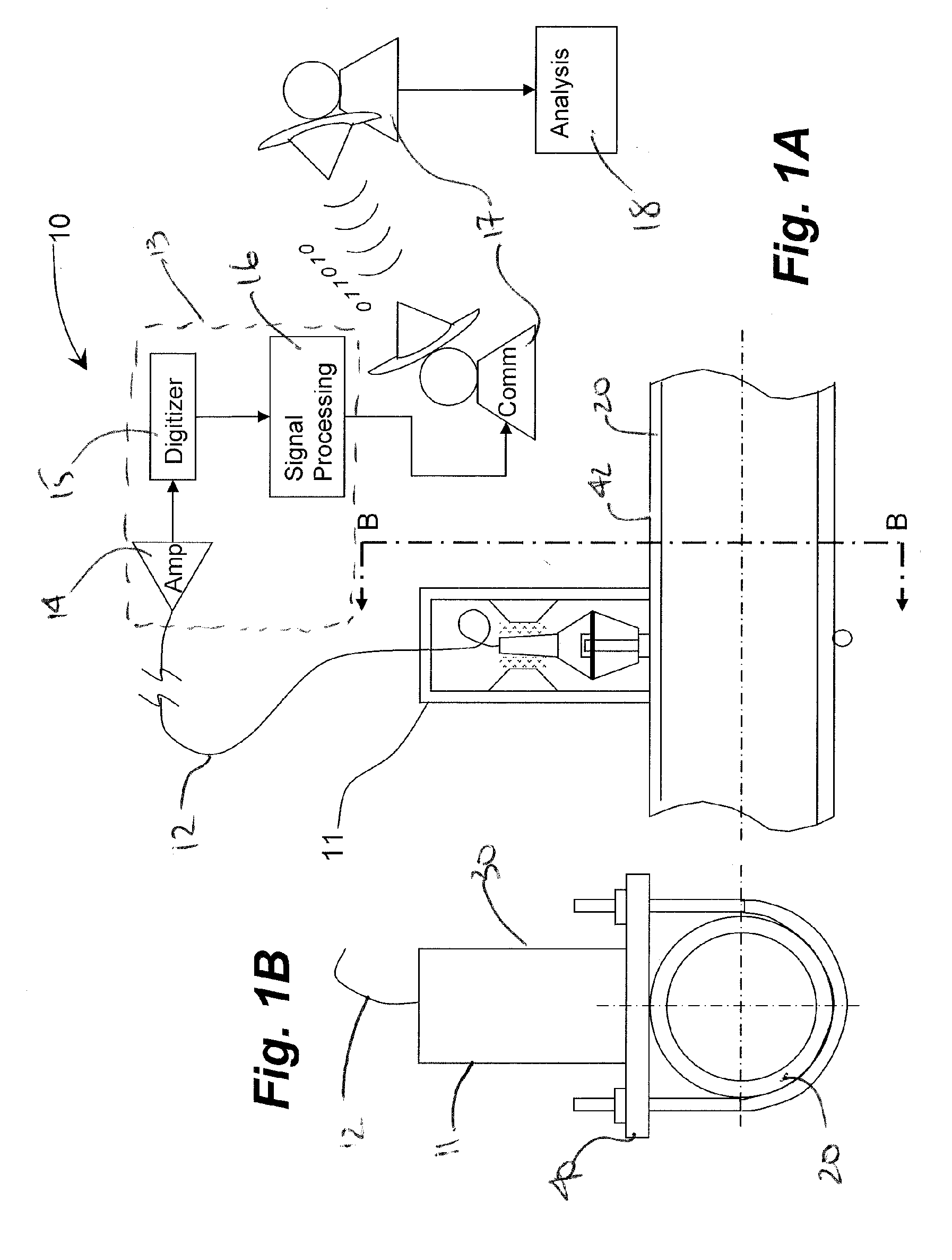
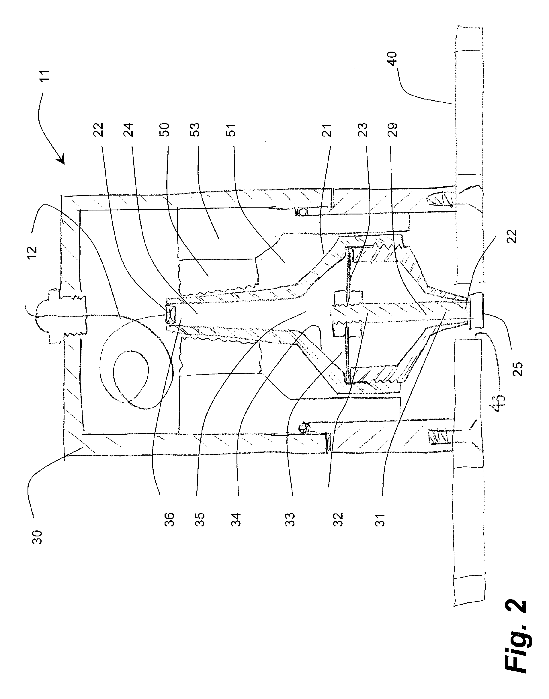
[0010] In one embodiment, a mechanical amplifier is retained in surface contact with a metallic conduit using a rare earth magnet. The mechanically amplified sound waves from fluid flowing in the conduit are received at a low power, condenser-type microphone. The power requirements of the microphone are minimal and can be determined to be at intrinsically safe levels. These first microphone signals are conducted outside of the intrinsically safe area to a radio frequency (RF) amplifier. While not the most accurate for audio frequencies, an RF amplifier is a lower power option for increasing the signal strength and delivering the raw amplified audio signal to a digitizer. This second digitized signal is received by a signal processor such as for the elimination of non-flow data (noise) and the remaining signal is related to a fluid flow rate. On-site processing can be managed by a microprocessor for periodic measurement and processing to conserve battery-power, particularly useful for remote un-serviced locations. A low power satellite transmitter can communicate a compact data packet of processed data for analysis at another location.
[0011] Use of such components results in very low power consumption so that stand-alone, battery-operated operation at remote sites is possible. This is accomplished through the selection of very low power devices, and a microprocessor which specifically controls power to all other devices.

Problems solved by technology

Other considerations are that sensors are unreliable in their repeatability due to methods and apparatus for mounting.
Conventional microphones require electronic amplification which introduces signal to noise considerations and require non-trivial power sources unsuitable for remote locations isolated from utilities.
Conventional data collection requires significant power and transmission of raw data requires large bandwidth and sophisticated communications.

Method used


Image

  • System, method and apparatus for acoustic fluid flow measurement
  • System, method and apparatus for acoustic fluid flow measurement
  • System, method and apparatus for acoustic fluid flow measurement

Examples


examples

[0065] With reference to FIGS. 6, 7A, 7B and 8, the output of an embodiment of the sensor above was compared against conventional flow measurement techniques. It is well known that flow rate of gas in conduits can be inferred by measuring the differential pressure drop across a known restriction, such as an orifice in a plate. Using a sensor, monitoring electronics, and signal processing techniques, it was shown that the acoustic energy directly correlates very well to the differential pressure across the orifice plate, and thus the acoustic energy correlates with the flow rate of the gas.

[0066] As shown in the comparative acoustic and convention differential pressure analysis of FIGS. 6-8, acoustic energy correlates well to differential pressure, which correlates to flow rate by well known square root calculation.

[0067] Testing of acoustically-determined flow rates were measured in conduits such as standard piping from 1.5″ diameter to 12″ diameter. The orientation of the pipes, ...


PUM


Abstract

An apparatus, system and methodology enable non-intrusive measurement of parameters related to fluid flow in a conduit. An acoustic sensor is located along the conduit and includes a mechanical amplifier having an acoustic input coupled to the conduit and a microphone coupled to the mechanical amplifier. The microphone receives mechanically amplified acoustic energy from the conduit and establishing first signals which are processed for generating second signals which are related to fluid flow in the conduit. The second signals can include quantitative flow data and qualitative data such as change in state and alarms. The second signals can be transmitted wirelessly to a remote site for further processing. Use of low power components and power management enable long term operations on battery power.

Description

FIELD OF THE INVENTION [0001] This invention relates to apparatus, systems and methodology for measuring acoustic characteristics of flow in a conduit for establishing rate of fluid flow therethrough. More particularly, battery powered, low power consumption components are combined for the acoustic measurement of flow including a mechanical amplifier, a microphone and on-site processing of acoustic flow data which can be transmitted off-site. BACKGROUND OF THE INVENTION [0002] Invasive flow measurement devices, such as orifice plates affect the flow itself. Measurement without orifice plate, or other restrictions applied for direct flow measurement, is particularly important in very low pressure systems where even the 1 to 5 psi pressure drop across an orifice cannot be tolerated. Such parameters are increasingly common in the flow produced from shallow gas wells and coal bed methane fields. [0003] Flow measurement using non-invasive acoustic characteristics of the fluid flowing the...

Claims


Application Information

Patent Timeline
IPC IPC(8): G01F1/00
CPCG01F1/666G01F15/14G01F15/063
Inventor CONQUERGOOD, STEVE
Owner ADVANCED FLOW TECH
Learn More