
Control system for adjustable damping force damper

a control system and damper technology, applied in the direction of shock absorbers, instruments, cycle equipment, etc., can solve the problems of deteriorating ride performance and uncomfortable passenger feelings, and achieve the effect of increasing the damping force of the damper and enhancing ride performan

Active Publication Date: 2006-10-05
HONDA MOTOR CO LTD
View PDF17 Cites 8 Cited by
  • Summary
  • Abstract
  • Description
  • Claims
  • Application Information

AI Technical Summary

Benefits of technology

[0008] The present invention has been made in view of the above circumstances, and it is an object of the present invention to enhance a ride performance when a vehicle gets over steps.
[0020] According to a configuration of the first aspect of the present invention, when the absolute value of the sprung speed generated when the vehicle get over the steps on the road surface exceeds a predetermined value upon setting the damping force of the damper of the suspension apparatus based on a product of the sprung speed and the gain, the gain used to calculate a target damping force is changed in response to a sign of the sprung speed. Therefore, a difference of the passenger's feeling, that is different between a case where the vehicle goes up onto the big steps and a case where the vehicle comes down from the big steps, can be solved by changing an damping force of the damper 14.
[0022] Therefore, since an increase of the sprung speed is permitted by increasing the damping force of the damper when the vehicle goes up onto the steps, the ride performance can be enhanced by dissolving a passenger's uncomfortable feeling such that the passenger feels to rise from the seat.

Problems solved by technology

Therefore, when a gain of the skyhook control is set uniformly in both situations, there are undesirable possibilities that the passenger may feel uncomfortable and a ride performance may be deteriorated.

Method used


Image

  • Control system for adjustable damping force damper
  • Control system for adjustable damping force damper
  • Control system for adjustable damping force damper

Examples


Embodiment Construction

[0029] An implementation mode of the present invention will be explained based on an embodiment of the present invention shown in the accompanying drawings hereinafter.

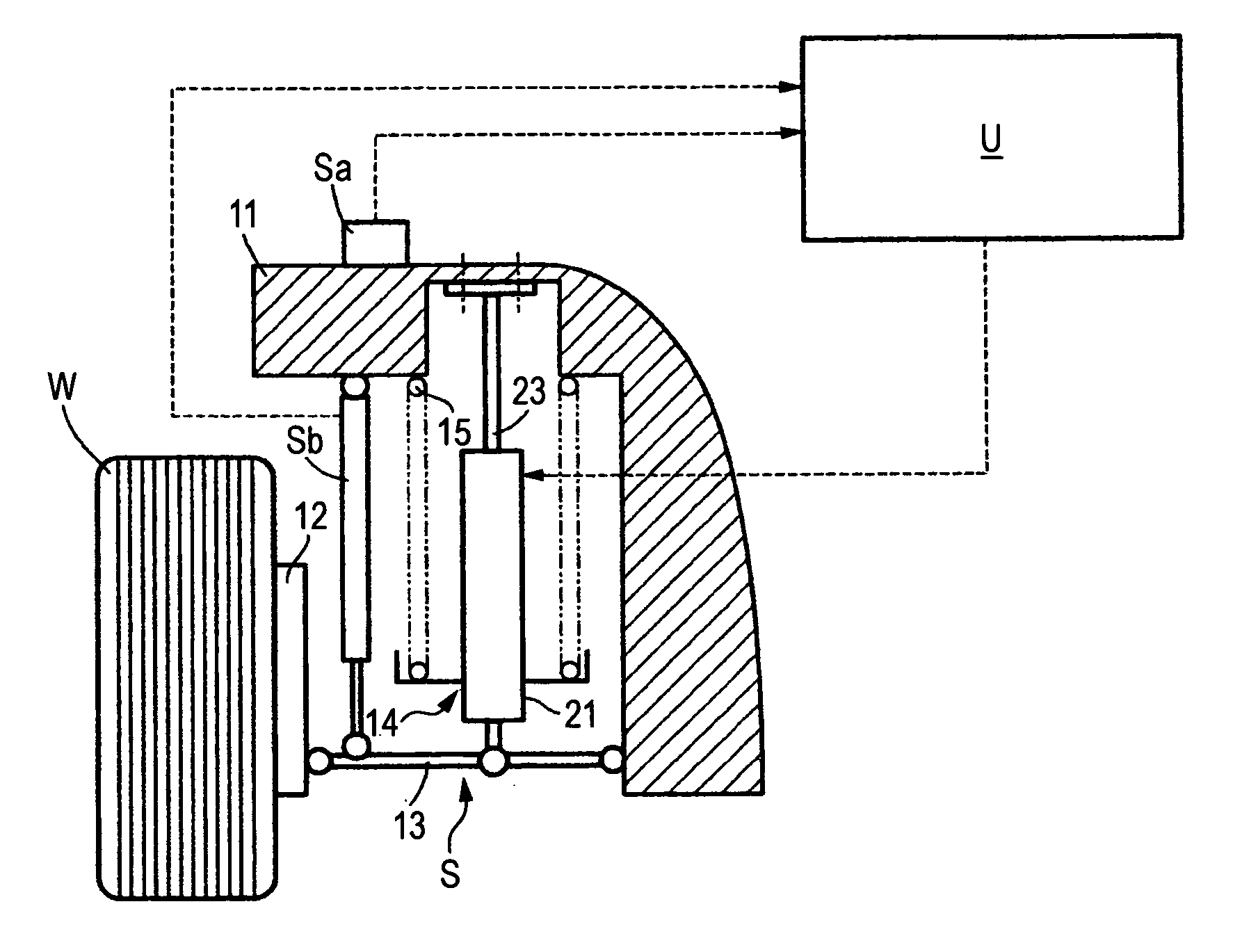
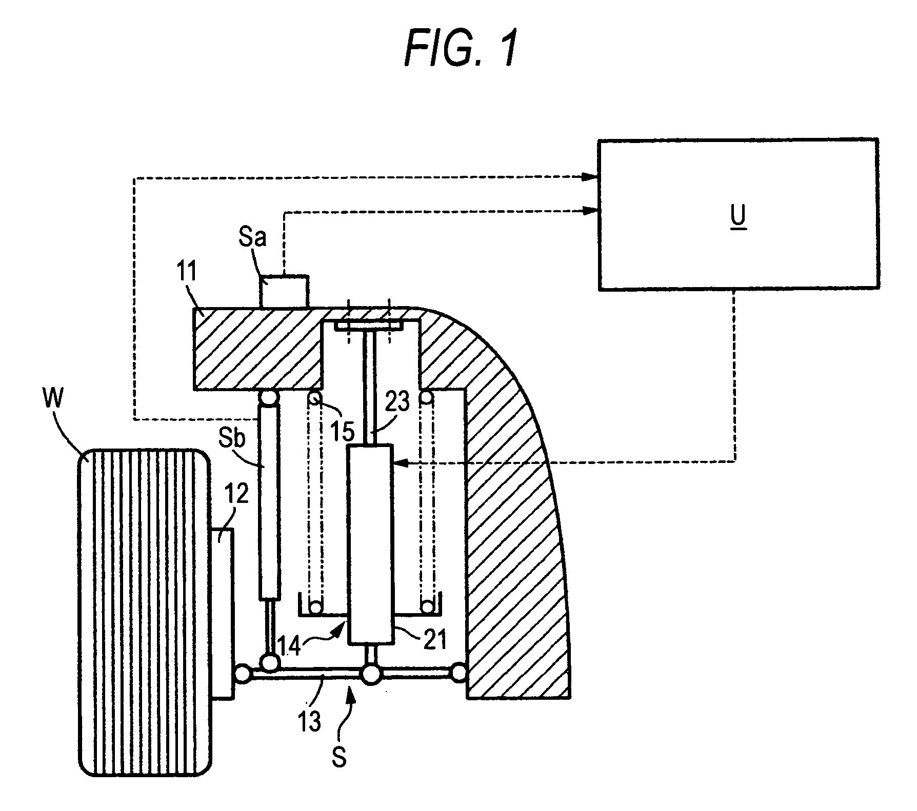
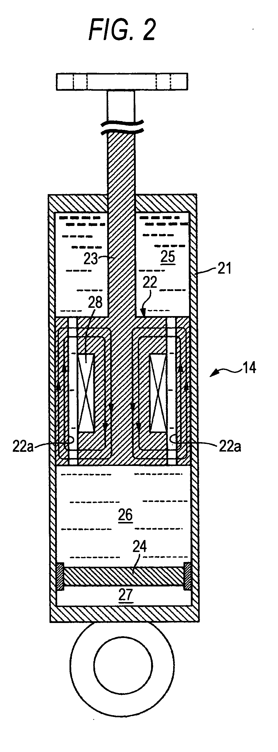
[0030]FIG. 1 to FIG. 6 show an embodiment of the present invention. FIG. 1 is a front view of a suspension apparatus of a vehicle, FIG. 2 is an enlarged sectional view of a adjustable damping force damper, FIG. 3 is a view showing a model of a suspension apparatus, FIG. 4 is an explanatory view of skyhook control, FIG. 5 is a view showing a state that a vehicle goes up onto steps and a state that a vehicle comes down from steps, and FIG. 6 is a graph showing a sprung speed when the vehicle goes up onto steps and when the vehicle comes down from steps.

[0031] As shown in FIG. 1, a suspension apparatus S that suspends a wheel W of a four-wheel vehicle includes a suspension arm 13 for supporting a knuckle 12 vertically and movably onto a vehicle body 11, a adjustable damping force damper 14 for connecting the suspension...


PUM


Abstract

A control system for a adjustable damping force damper includes a damper and a spring provided on a suspension apparatus of a vehicle, a sprung speed sensor for detecting speed of an upper member of the spring, the sprung speed is generated when the vehicle gets over steps on a road surface and a control unit for setting a gain so as to determine an damping force of the damper based on a product of the sprung speed and the gain. When an absolute value of the sprung speed exceeds a predetermined value, the control unit changes the gain in response to a positive sign or a negative sign of the sprung speed.

Description

[0001] The present invention claims foreign priority to Japanese patent application No. P.2005-098166, filed on Mar. 30, 2005, the contents of which is incorporated herein by reference. BACKGROUND OF THE INVENTION [0002] 1. Field of the Invention [0003] The present invention relates to a control system for a adjustable damping force damper, which controls variably an adjustable damping force of a damper provided to a suspension apparatus of a vehicle in response to a moving condition of the vehicle. [0004] 2. Description of the Background Art [0005] In Japanese Patent Unexamined Publication No. JP-A-60-113711, the adjustable damping force damper in which MRF (Magneto-Rheological Fluids), whose viscosity is changed by applying a magnetic field, is employed as a viscous fluid of the adjustable damping force damper for the suspension apparatus and also a coil used to apply the magnetic field to the magneto-rheological fluids in the fluid passage is provided to a piston, which is slidab...

Claims


Application Information

Patent Timeline
IPC IPC(8): B60G17/018
CPCB60G17/0165B60G17/08B60G2400/102B60G2400/202B60G2600/22B60G2400/252B60G2500/10B60G2600/184B60G2400/206
Inventor IZAWA, MASAKIKATO, TAKAFUMI
Owner HONDA MOTOR CO LTD
Learn More