Terminal device

a terminal device and terminal technology, applied in the direction of digital transmission, data switching network, instruments, etc., can solve the problems of difficult to individually identify the device from remote places, difficult to judge at a glance whether an image formation device is suitable, and difficult to execute printing-out operations

Inactive Publication Date: 2006-10-05
BROTHER KOGYO KK
View PDF9 Cites 46 Cited by
  • Summary
  • Abstract
  • Description
  • Claims
  • Application Information

AI Technical Summary

Problems solved by technology

When the PC makes the image formation device execute the printing-out operation via the network, it is difficult to impossible to execute the printing-out operation in the case where a destination to which print data is to be sent is not assigned.
In such a case, it is often hard to individually identify the devices from remote places.
However, there is a problem that it is difficult to judge at a glance whether an image formation device is a device that the user himself has assigned to the destination to which the print data is to be sent (i.e., the operation target).
In addition, in the printing system disclosed in '559 publication, such an image formation device that detailed data on its location is required to be previously inputted to a printer location database by a user, or such an image formation device that its location has to be confirmed based upon a floor map prepared with its location being shown thereon together with its IP address and / or serial number, there is required not only trouble of preparing necessary materials and configuring necessary settings, but also a lot of trouble of maintenance, since the materials and settings have to be changed every time the installation location thereof is changed.
In this case, since the IP address or serial number is represented as only arrangement of characters, even though such kind of information is displayed, it is hard to confirm at a glance the location of the image formation device.
In this case, since the user has to operate the image formation device with coming and going between the PC and the image formation device, the user is forced to perform troublesome operations.
There is a further problem that the user has to break the use of the image formation device during the operation for confirming the location thereof, accompanied by operating the image formation device.

Method used


Image

  • Terminal device
  • Terminal device
  • Terminal device

Examples


Embodiment Construction

[0034] It is noted that various connections are set forth between elements in the following description. It is noted that these connections in general and, unless specified otherwise, may be direct or indirect and that this specification is not intended to be limiting in this respect.

[0035] General Overview

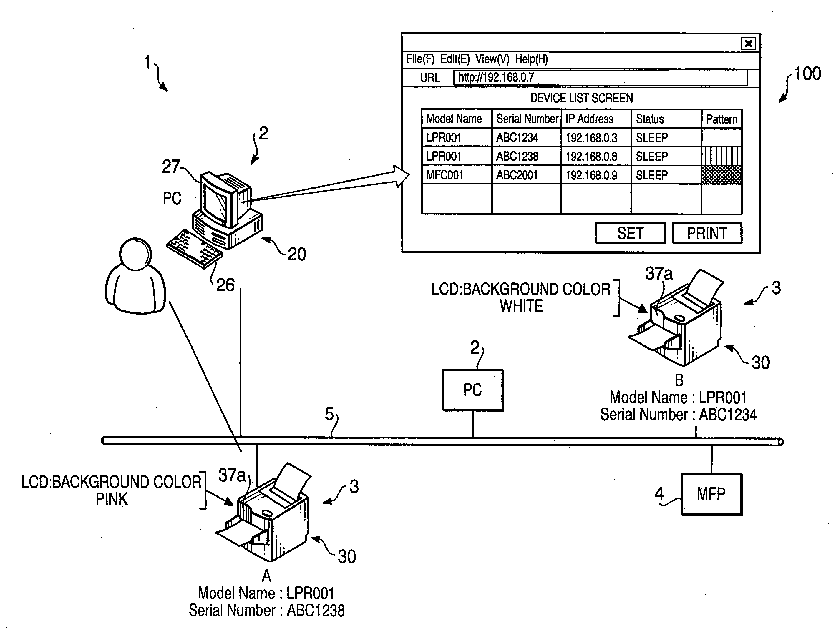
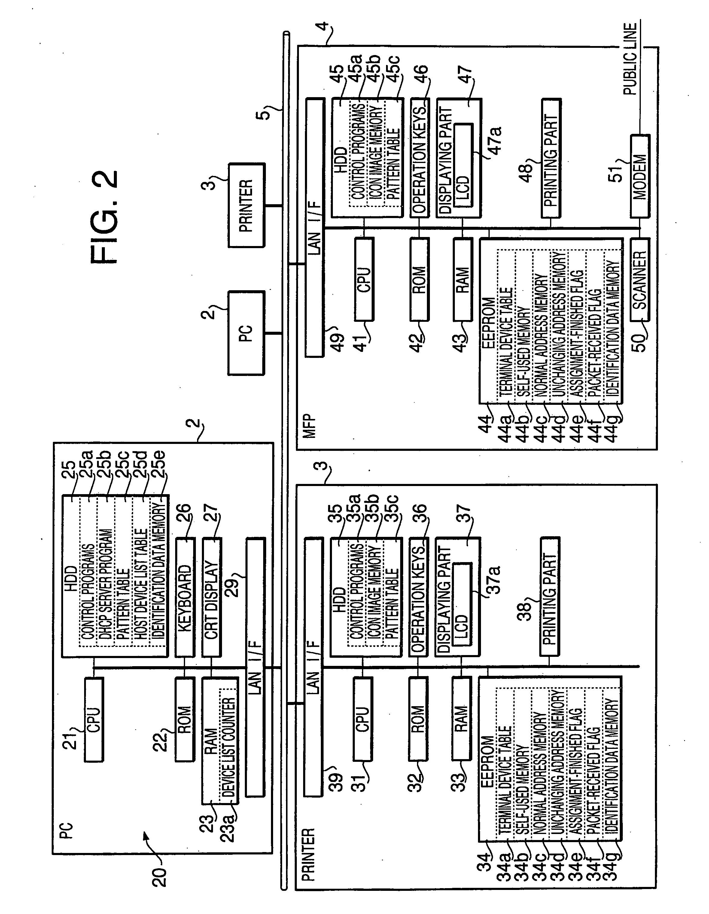
[0036] According to aspects of the present invention, there is provided a terminal device, which includes: an output device configured to output information; a self-pattern storing system configured to store information on an expression pattern for the terminal device therein; a configuring system configured to configure the information on the expression pattern for the terminal device into the self-pattern storing system; an output executing system configured to make the output device output the expression pattern for the terminal device, based upon the information on the expression pattern for the terminal device; an obtaining system configured to obtain information on express...


PUM


Abstract

A terminal device, which is to be connected to the network together with other terminal devices and a host device to operate the terminal device, includes an output device that outputs perceptually recognized information, a self-pattern storing system that stores information on an expression pattern for the terminal device, a configuring system that configures the information into the self-pattern storing system, an output executing system that makes the output device output the expression pattern, based upon the written information, an obtaining system that obtains information on expression patterns for the other terminal devices, and a setting system that defines an expression pattern different from any of the expression patterns for the other terminal devices as the expression pattern for the terminal device, based upon the obtained information, and sets information on the defined expression pattern as the information to be written.

Description

CROSS-REFERENCE TO RELATED APPLICATION [0001] This application claims priority under 35 U.S.C. §119 from Japanese Patent Application No. 2005-105521, filed on Mar. 31, 2005. The entire subject matter of the application is incorporated herein by reference. BACKGROUND [0002] 1. Technical Field [0003] The following description relates to one or more techniques that allows a user to individually identify a plurality of terminal devices interconnected via a network with different expressions given by the plurality of terminal devices from each other. [0004] 2. Related Art [0005] Image formation devices, such as printers and MFPs (Multi Function Peripherals), are generally provided with a display screen for displaying an operation procedure etc. in order to improve operability thereof. Some of the image formation devices can arbitrarily change a color of an image displayed on the display screen depending on the kind of the image. Each of such image formation devices is configured such tha...

Claims


Application Information

Patent Timeline
Patent Type & Authority Applications(United States)
IPC IPC(8): H04L12/28
CPCG06F3/1206G06F3/1253H04L61/2015H04L29/12226G06F3/1286H04L61/5014
Inventor ISHIMOTO, KANWAKAZONO, TOMOMI
Owner BROTHER KOGYO KK
Why Eureka
Try Eureka