Multi-winding motor
a multi-winding, motor technology, applied in the direction of dynamo-electric machines, synchronous generators, electrical apparatus, etc., can solve the problems of increasing cost, impractical motor drive system, impedance unbalance or fluctuation of n f-phase exciting windings, etc., to improve the impedance unbalance of multi-phase exciting windings
- Summary
- Abstract
- Description
- Claims
- Application Information
AI Technical Summary
Benefits of technology
Problems solved by technology
Method used
Image
Examples
first embodiment
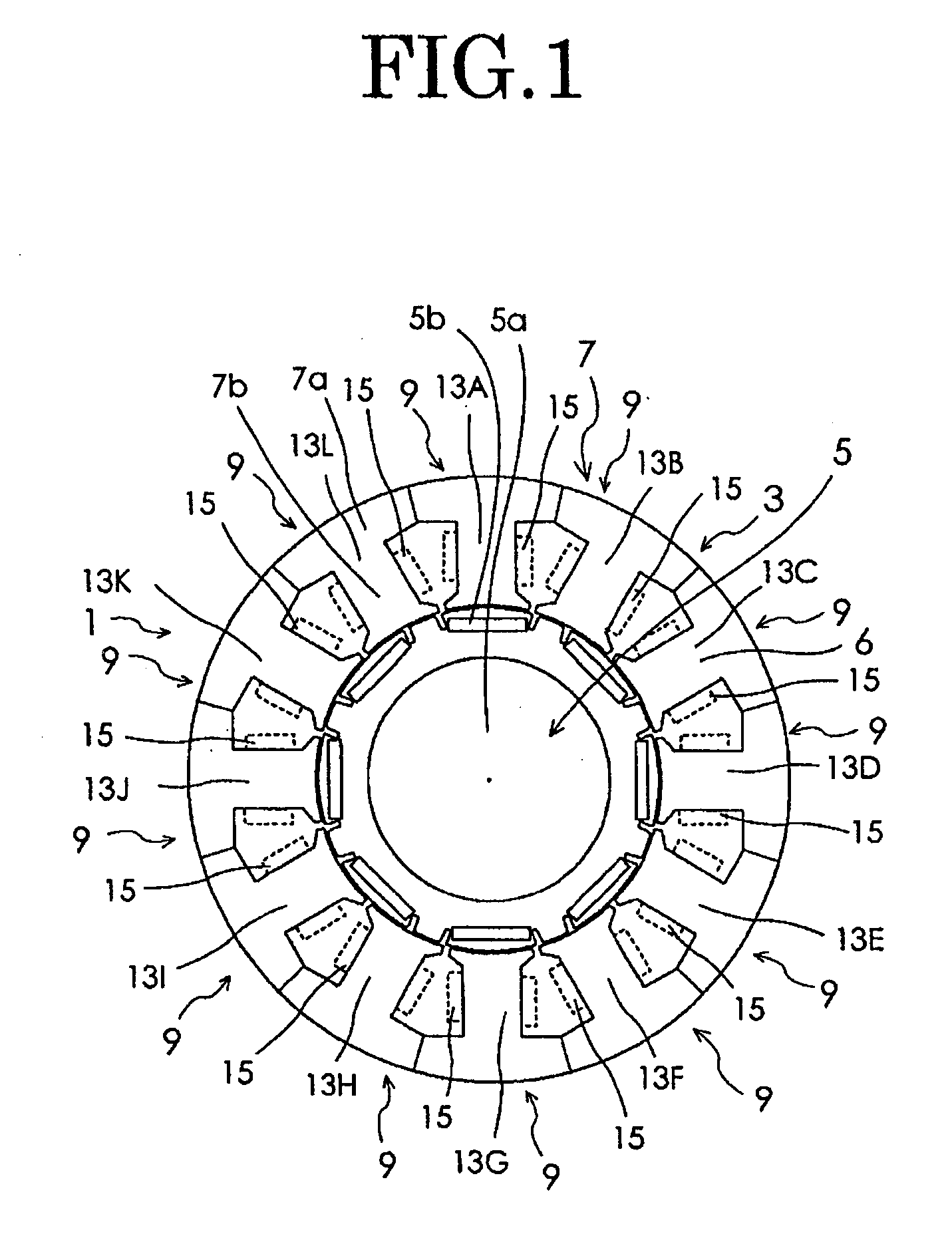
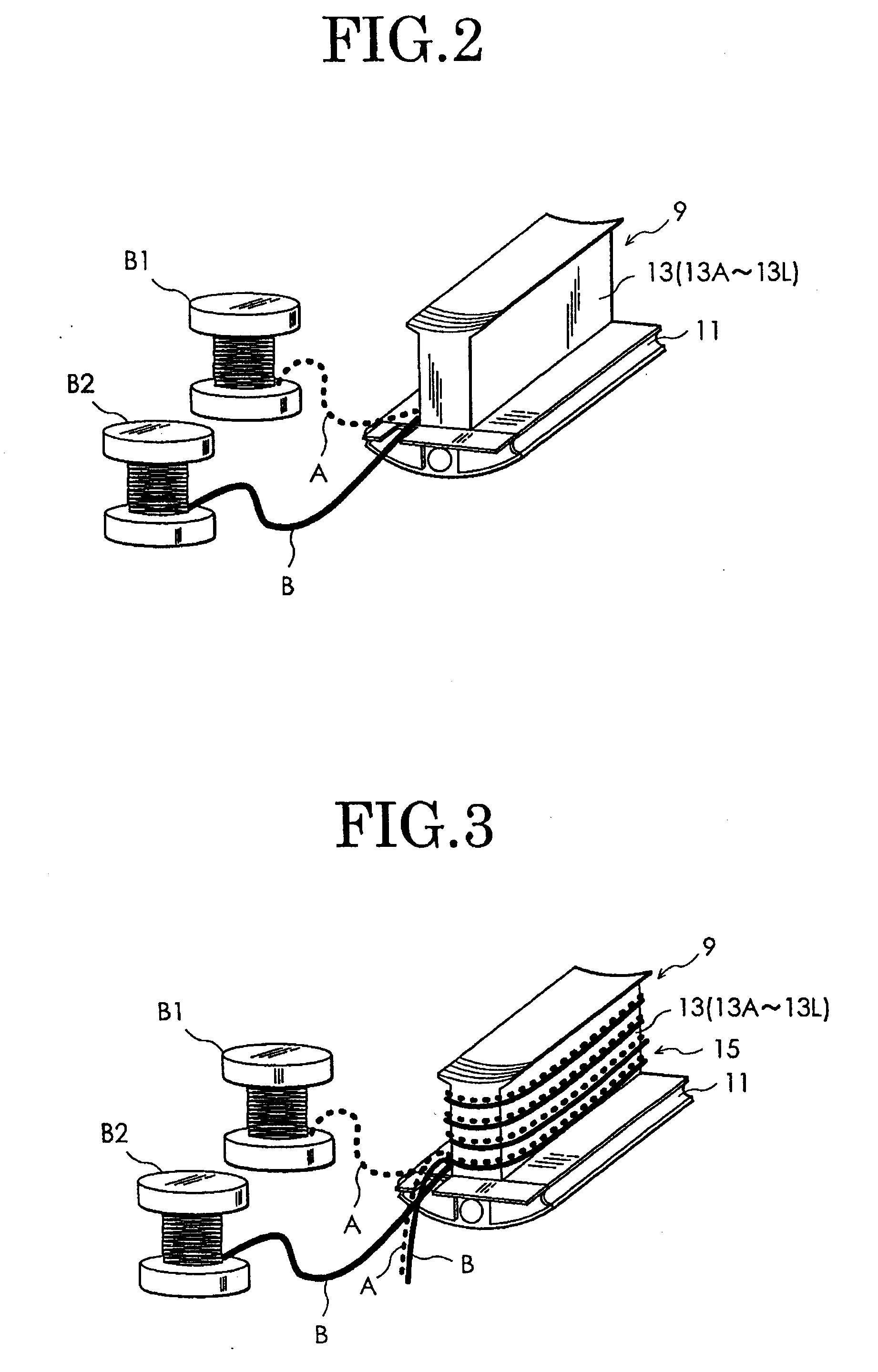
[0033] Now, the best mode for carrying out the present invention will be described in detail with reference to the accompanying drawings. FIG. 1 is a cross sectional view of a multi-winding motor according to the present invention. As shown in FIG. 1, a multi-winding motor 1 of the embodiment has a stator 3 and a rotor 5. The rotor 5 includes a rotor core 5a having a substantially columnar shape and eight plate-type permanent magnets 5b constituting magnetic pole sections, embedded in the vicinity of an surface portion of the rotor core 5a at regular intervals in a circumferential direction of the rotor core. The stator 3 includes a stator core 7. The stator core 7 is constructed from twelve divided cores 9 which are annularly arranged. The divided core 9 is integrally formed of a yoke constituent section 11 and a magnetic pole section 13 in a T-letter relation as shown in FIG. 2. Therefore, the stator core 7 has F×M (F and M are an integer of 2 or more) magnetic pole sections 13A-1...
second embodiment
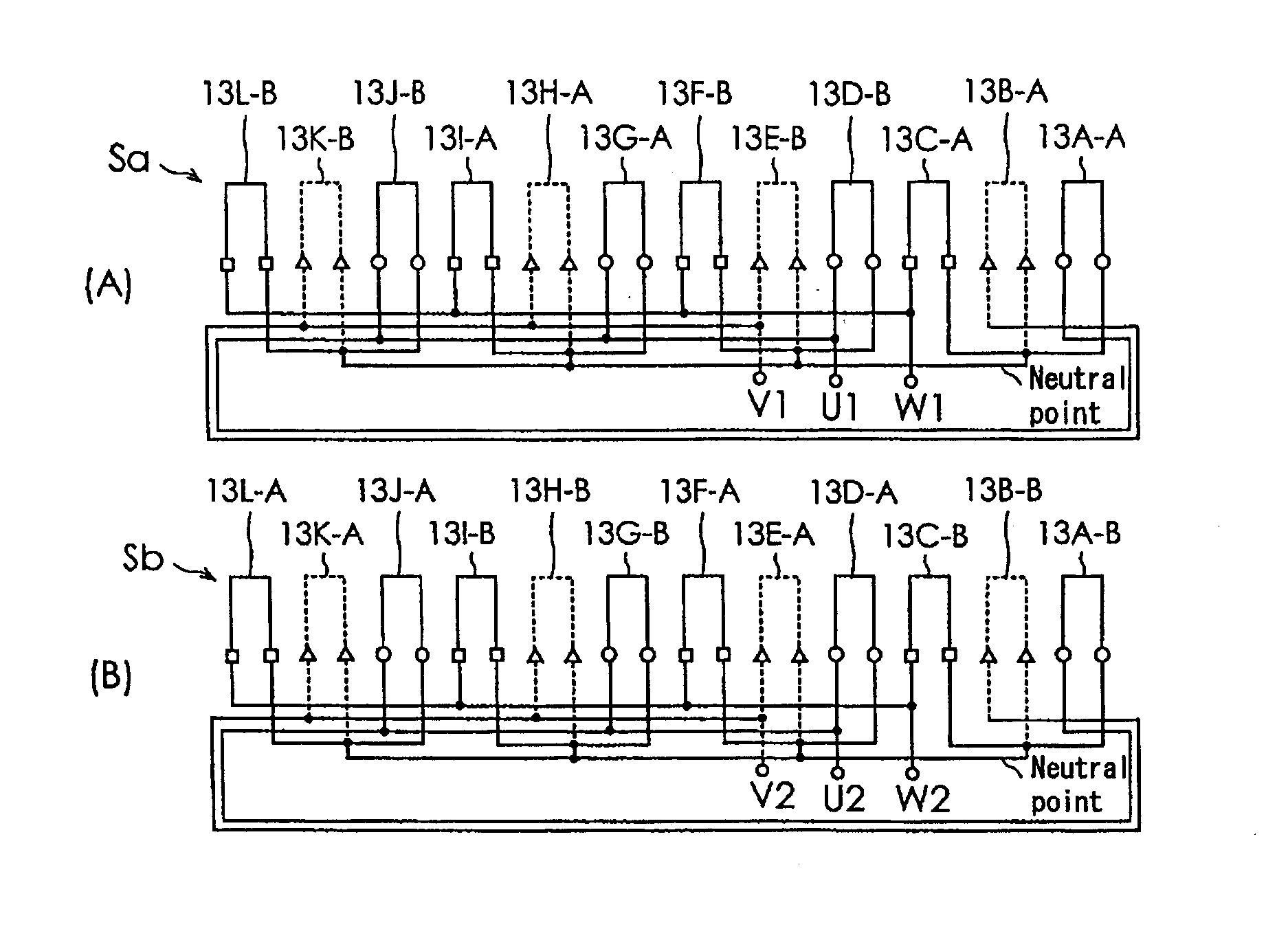
[0040] FIGS. 8(A) and (B) are illustrations showing a multi-winding motor of the present invention, in which discrete winding wirings A, B are connected in series with each other. As shown in FIG. 8(A), the first three-phase exciting winding Sa of the multi-winding motor according to the embodiment is constructed from an exciting winding U1, an exciting winding V1 and an exciting winding W1, which are star-connected with each other as shown in FIG. 8(A). The exciting winding U1 for one phase (U-phase) is constructed from four (M) discrete winding wirings A, B, A, B, which are selected one by one from the two (N) kinds of discrete winding wirings A, B provided at each of the four (M) magnetic pole sections (magnetic pole sections wound with the discrete winding wirings A, B of the U-phase winding sections 15) 13A, 13D, 13G, 13J selected from twelve (F×M) magnetic pole sections 13A-13L, and are connected in that order in series with each other. Specifically, the exciting winding U1 is...
third embodiment
[0043] FIGS. 9(A) and 9(B) are illustrations showing how two (first and second) discrete winding wirings A, B of the three-phase exciting windings Sa, Sb are connected in a combination of series and parallel connections in a multi-winding motor according to the present invention.
[0044] FIGS. 9(A) and (B) are illustrations showing a multi-winding motor according to a third embodiment of the present invention, in which the discrete winding wirings A, B are connected with each other in a combination of series and parallel connections. The first three-phase exciting winding Sa of the multi-winding motor according to this embodiment is constructed from an exciting winding U1, an exciting winding V1 and an exciting winding W1, which are star-connected with each other as shown in FIG. 9(A). The exciting winding U1 for one phase (U-phase) is constructed from four (M) discrete winding wirings A, B, A, B, which are selected one by one from two (N) kinds of discrete winding wirings A, B provid...
PUM
 Abstract
Description
Claims
Application Information
 - R&D
- Intellectual Property
- Life Sciences
- Materials
- Tech Scout
- Unparalleled Data Quality
- Higher Quality Content
- 60% Fewer Hallucinations
Browse by: Latest US Patents, China's latest patents, Technical Efficacy Thesaurus, Application Domain, Technology Topic, Popular Technical Reports.
© 2025 PatSnap. All rights reserved.Legal|Privacy policy|Modern Slavery Act Transparency Statement|Sitemap|About US| Contact US: help@patsnap.com


