
Optimized network resource location

a network resource and location technology, applied in the field of computer network replication, can solve the problems of imposing a heavy traffic burden on the entire network, increasing the strain on the supply, and further exacerbated the problem, and achieve the effect of low cos

Inactive Publication Date: 2006-09-28
MOUNT SHASTA ACQUISITION +2
View PDF100 Cites 155 Cited by
  • Summary
  • Abstract
  • Description
  • Claims
  • Application Information

AI Technical Summary

Benefits of technology

This approach enhances network performance by efficiently distributing load across servers, reducing the need for costly hardware upgrades and improving cache efficiency by ensuring fresh data is served, while allowing for fine-grained control over resource access and caching.

Problems solved by technology

The rapid growth in popularity of the Internet has imposed a heavy traffic burden on the entire network.
Solutions to problems of demand (e.g., better accessibility and faster communication links) only increase the strain on the supply.
The adoption of content-rich applications, such as live audio and video, has further exacerbated the problem.
These increments are not always as fine-grained as the publisher needs, and quite often lead times can cause the publisher's Web site capacity to lag behind demand.
To address more serious bandwidth growth problems, publishers may develop more complex and costly custom solutions.
These solutions, however, are difficult and expensive to deploy and operate.
As a result, only the largest publishers can afford them, since only those publishers can amortize the costs over many customers (and Web site hits).
In general, these technologies are designed for use by a single Web site and do not include features that allow their components to be shared by many Web sites simultaneously.
Database systems are particularly difficult to replicate, as they are continually changing.
Several mechanisms allow for replication of databases, although there are no standard approaches for accomplishing it.
Once a Web site is served by multiple servers, a challenge is to ensure that the load is appropriately distributed or balanced among those servers.
Assuming that client protocols cannot easily change, there are two major problems in the deployment of replicated resources.
These hints are predictive, and are necessarily often incorrect, so proxy caches frequently serve stale data.
Once a resource is cached, the publisher has no way of knowing how often it was accessed from the cache.

Method used


Image

  • Optimized network resource location
  • Optimized network resource location
  • Optimized network resource location

Examples


Embodiment Construction

[0030] Overview

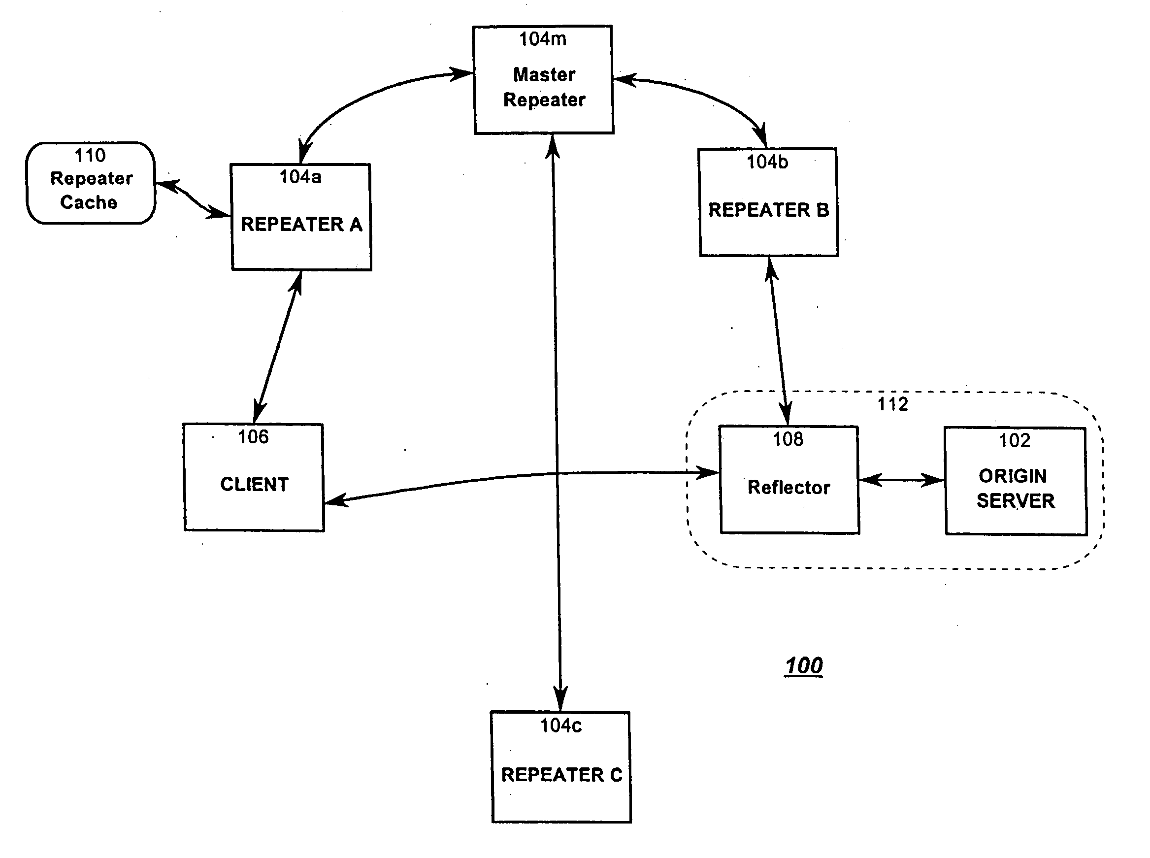
[0031]FIG. 1 shows a portion of a network environment 100 according to the present invention, wherein a mechanism (reflector 108, described in detail below) at a server (herein origin server 102) maintains and keeps track of a number of partially replicated servers or repeaters 104a, 104b, and 104c. Each repeater 104a, 104b, and 104c replicates some or all of the information available on the origin server 102 as well as information available on other origin servers in the network 100. Reflector 108 is connected to a particular repeater known as its “contact” repeater (“Repeater B”104b in the system depicted in FIG. 1). Preferably each reflector maintains a connection with a single repeater known as its contact, and each repeater maintains a connection with a special repeater known as its master repeater (e.g., repeater 104m for repeaters 104a, 104b and 104c in FIG. 1).

[0032] Thus, a repeater can be considered as a dedicated proxy server that maintains a partial or s...


PUM


Abstract

Resource requests made by clients of origin servers in a network are intercepted by reflector mechanisms and selectively reflected to other servers called repeaters. The reflectors select a best repeater from a set of possible repeaters and redirect the client to the selected best repeater. The client then makes the request of the selected best repeater. The resource is possibly rewritten to replace at least some of the resource identifiers contained therein with modified resource identifiers designating the repeater instead of the origin server.

Description

1. FIELD OF THE INVENTION [0001] This invention relates to replication of resources in computer networks. 2. BACKGROUND OF THE INVENTION [0002] The advent of global computer networks, such as the Internet, have led to entirely new and different ways to obtain information. A user of the Internet can now access information from anywhere in the world, with no regard for the actual location of either the user or the information. A user can obtain information simply by knowing a network address for the information and providing that address to an appropriate application program such as a network browser. [0003] The rapid growth in popularity of the Internet has imposed a heavy traffic burden on the entire network. Solutions to problems of demand (e.g., better accessibility and faster communication links) only increase the strain on the supply. Internet Web sites (referred to here as “publishers”) must handle ever-increasing bandwidth needs, accommodate dynamic changes in load, and improv...

Claims


Application Information

Patent Timeline
Patent Type & Authority Applications(United States)
IPC IPC(8): G06F15/173G06F12/00G06F9/50G06F13/00G06F15/00G06F17/30H04L29/06H04L29/08H04L29/12
CPCG06F9/505G06F17/30899H04L29/06H04L29/12066H04L29/12594H04L43/065H04L43/0817H04L43/16H04L61/1511H04L61/301H04L2029/06054H04L67/1095H04L67/2804H04L67/1008H04L67/1036H04L67/2895H04L67/322H04L67/2814H04L67/2819H04L67/125H04L67/1006H04L67/101H04L67/1021H04L67/02H04L67/2842H04L67/1002H04L67/28H04L67/1025H04L67/2852H04L67/1014H04L67/1012H04L67/1019H04L67/1023G06F2209/509G06F16/957H04L67/10015H04L61/4511H04L61/30H04L67/561H04L67/1001H04L67/564H04L67/563H04L67/56H04L67/5682H04L67/61H04L67/568H04L9/40
Inventor FARBER, DAVID A.GREER, RICHARD E.SWART, ANDREW D.BALTER, JAMES A.
Owner MOUNT SHASTA ACQUISITION
Learn More