Bone screw

a bone screw and screw head technology, applied in the field of bone screws, can solve the problems of only one thread in the thread section, enlargement of the cross sectional area of the bone material, etc., and achieve the effects of not having an excessively large cutting angle, reducing width, and improving retention

Inactive Publication Date: 2006-09-28
AO TECH AG +1
View PDF10 Cites 39 Cited by
  • Summary
  • Abstract
  • Description
  • Claims
  • Application Information

AI Technical Summary

Benefits of technology

The present invention provides a bone screw with a threaded shaft that can be cut concentrically with the axis of the screw into soft bone material. This is achieved by a knife-like element at the front end of the threaded section, which allows for a symmetrical distribution of forces during the cutting of the thread. The knife-like element has a cutting edge with a sector angle between 10° and 60°, which reduces the risk of micro or macro fractures in the bone material. The bone screw also has a larger working surface crossway and better retention in osteoporotic bones. The knife-like element can be constructed with a cutting angle between 10° and 60° and a sharp cutting edge can be produced at the tip of the threaded section. The bone screw can be used for flat bone fragments and has a conical facet for better retention. The invention provides a solution to the problem of bone screws that can cause micro or macro fractures in the bone material.

Problems solved by technology

(See U.S. Pat. No. 6,158,939 to Grossberndt) A disadvantage of the Grossberndt screw is that the threaded section includes only one thread.
This can lead to a wobbly, eccentric cutting process that results in a cross sectional enlargement in the bone material.

Method used


Image

  • Bone screw
  • Bone screw
  • Bone screw

Examples


Embodiment Construction

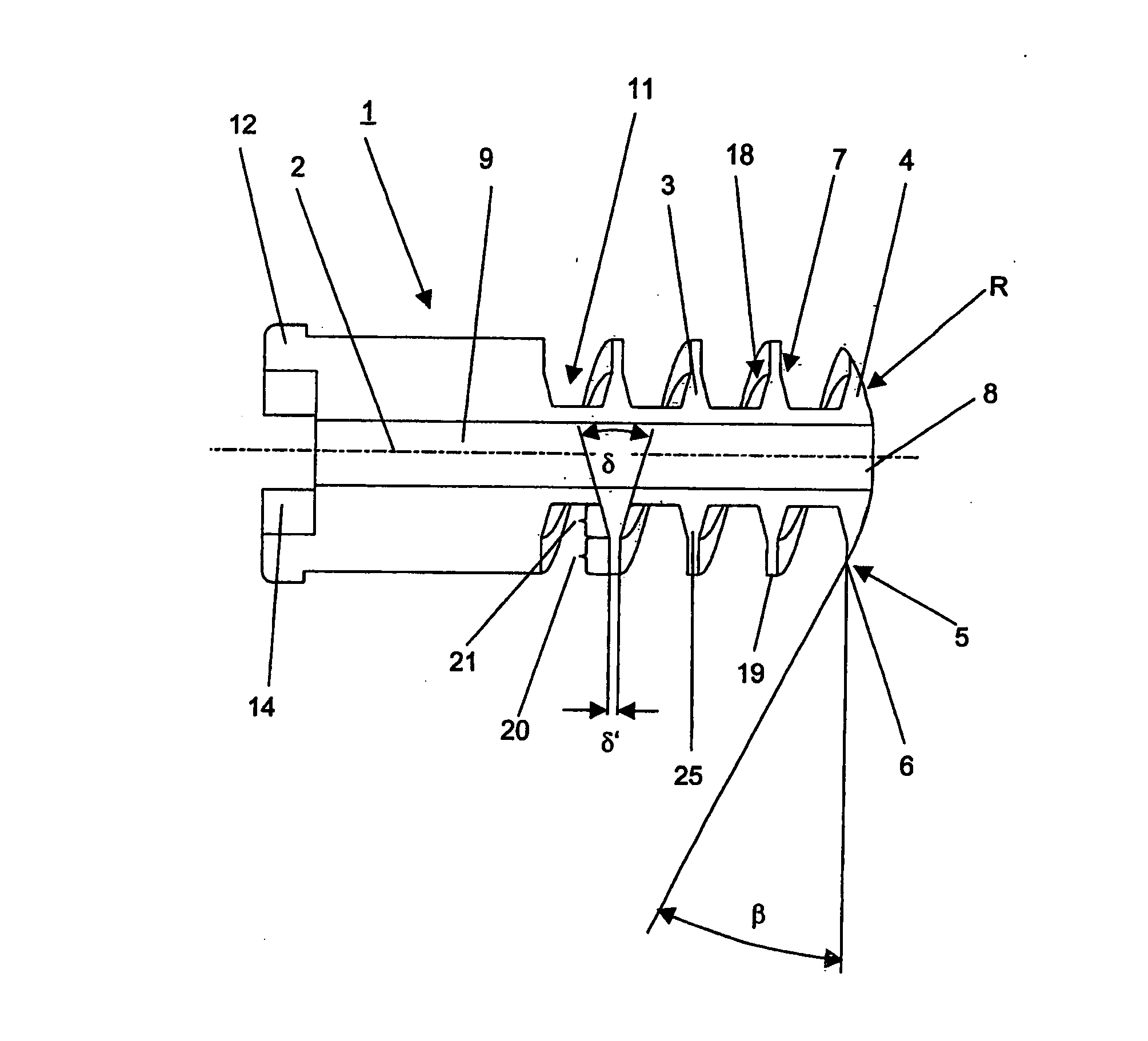
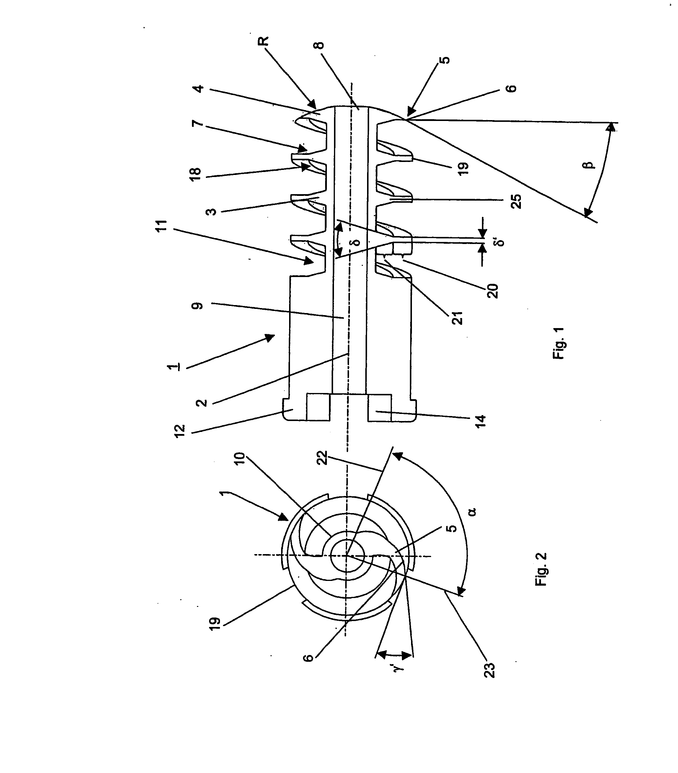
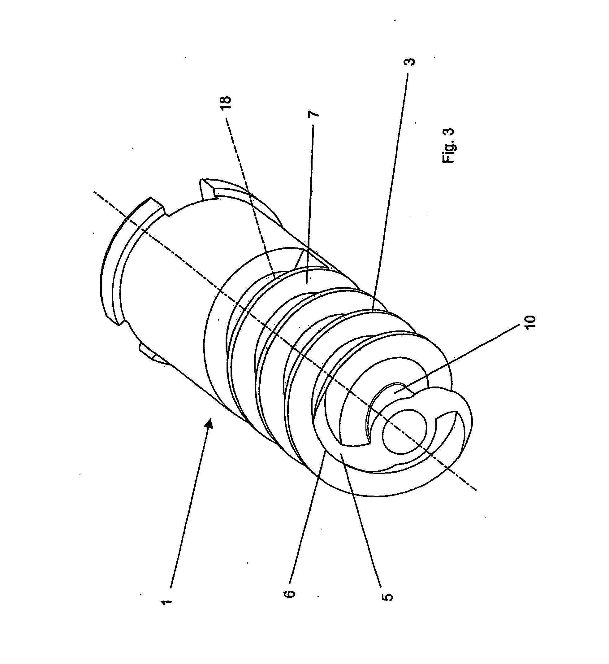
[0025] FIGS. 1 to 3 depict a preferred embodiment of the bone screw 1. The bone screw 1 comprises a threaded shaft 15. The threaded shaft 15 has a thread 3 having an outer diameter DA, a frontal thread end 4 and a thread profile 11. The thread profile 11 includes a frontal thread flank 7 which is directed towards the frontal thread end 4, and a rear thread flank 18. The bone screw 1 has a longitudinal axis 2. For accommodating a guide wire, the bone screw 1 is provided with a central borehole 9, which is coaxial with its longitudinal axis 2.

[0026] In a preferred embodiment, the thread 3 is a multipath, preferably a double path thread (double thread) where each thread path of the thread 3 at the frontal thread end 4 comprises a blade-type (knife-like) element 5 that may be sickle-shaped with a convexly curved cutting edge 6 disposed between the core 10 and the tip 19 of the threaded section 3. At the tip 19 of the threaded section 3, the cutting edge 6 changes over with a local cutt...


PUM


Abstract

A bone screw having a threaded shaft 15 which has a thread having an outer diameter DA, a frontal thread end and a thread profile. The thread profile has a frontal thread flank which is directed towards the frontal thread end 4, a rear thread flank 18 and a flank angle δ. The thread is multipath, preferably a double path thread where each thread path has a blade-type element with a cutting edge on the frontal thread end. The bone screw 1 also has a longitudinal axis 2. For accommodating a guide wire, the bone screw 1 is provided with a central borehole 9, which is coaxial with its longitudinal axis 2.

Description

TECHNICAL FIELD [0001] The present invention generally relates to a bone screw. BACKGROUND OF THE INVENTION [0002] A screw with a self-cutting threaded section for plastic materials, which includes, at the front end of the threaded section, a knife-like element, is known in the art. (See U.S. Pat. No. 6,158,939 to Grossberndt) A disadvantage of the Grossberndt screw is that the threaded section includes only one thread. Because of the single, knife-like element, the load on the bone screw while cutting the threaded section is asymmetric and a radial force is exerted on the bone screw which leads to a lateral migration of the tip of the screw. This can lead to a wobbly, eccentric cutting process that results in a cross sectional enlargement in the bone material. The threads, cut in this manner into the bone material, are larger than the thread profile of the bone screw, as a result, the hold of the bone screw in the bone material is decreased. SUMMARY OF THE INVENTION [0003] The pres...

Claims


Application Information

Patent Timeline
Patent Type & Authority Applications(United States)
IPC IPC(8): A61B17/58A61B17/00A61B17/74A61B17/86
CPCA61B17/74A61B17/8635A61B17/864A61B17/8645
Inventor MUNRO, CHADSENN, PETER
Owner AO TECH AG
Why Eureka
Try Eureka