
High resolution localization for indoor environments

a high-resolution, indoor environment technology, applied in the direction of wireless communication, electrical equipment, selection arrangements, etc., can solve the problem of poor gps reception inside the building

Inactive Publication Date: 2006-09-28
3COM
View PDF6 Cites 134 Cited by
  • Summary
  • Abstract
  • Description
  • Claims
  • Application Information

AI Technical Summary

Benefits of technology

[0007] The present invention relates to locating a person who is operating a wireless communications device in an indoor environment. In particular, it relates to processing various combinations of RSSI, direction of arrival and flight time characteristics of a signal, as received at two or more and preferably three or more access points. In one embodiment, the access points implement a wireless LAN (WLAN) and the communications device is a telephone operating over the WLAN. In another embodiment, the localization of a wireless device allows a system to reject users who are outside a predefined physical area. Particular aspects of the present invention are described in the claims, specification and drawings.

Problems solved by technology

However, GPS reception is poor inside of buildings.

Method used


Image

  • High resolution localization for indoor environments
  • High resolution localization for indoor environments
  • High resolution localization for indoor environments

Examples


Embodiment Construction

[0011] The following detailed description is made with reference to the figures. Preferred embodiments are described to illustrate the present invention, not to limit its scope, which is defined by the claims. Those of ordinary skill in the art will recognize a variety of equivalent variations on the description that follows.

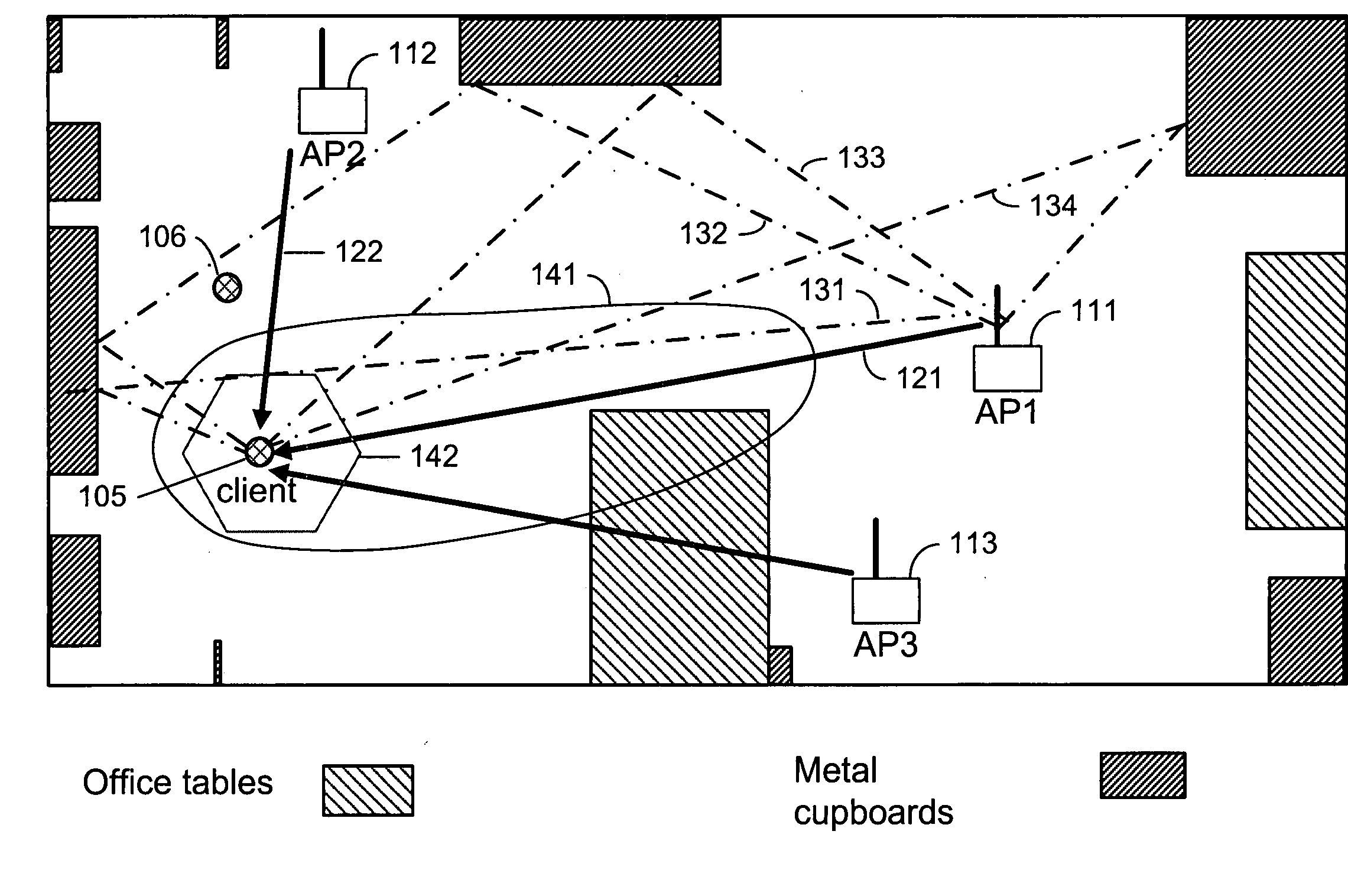
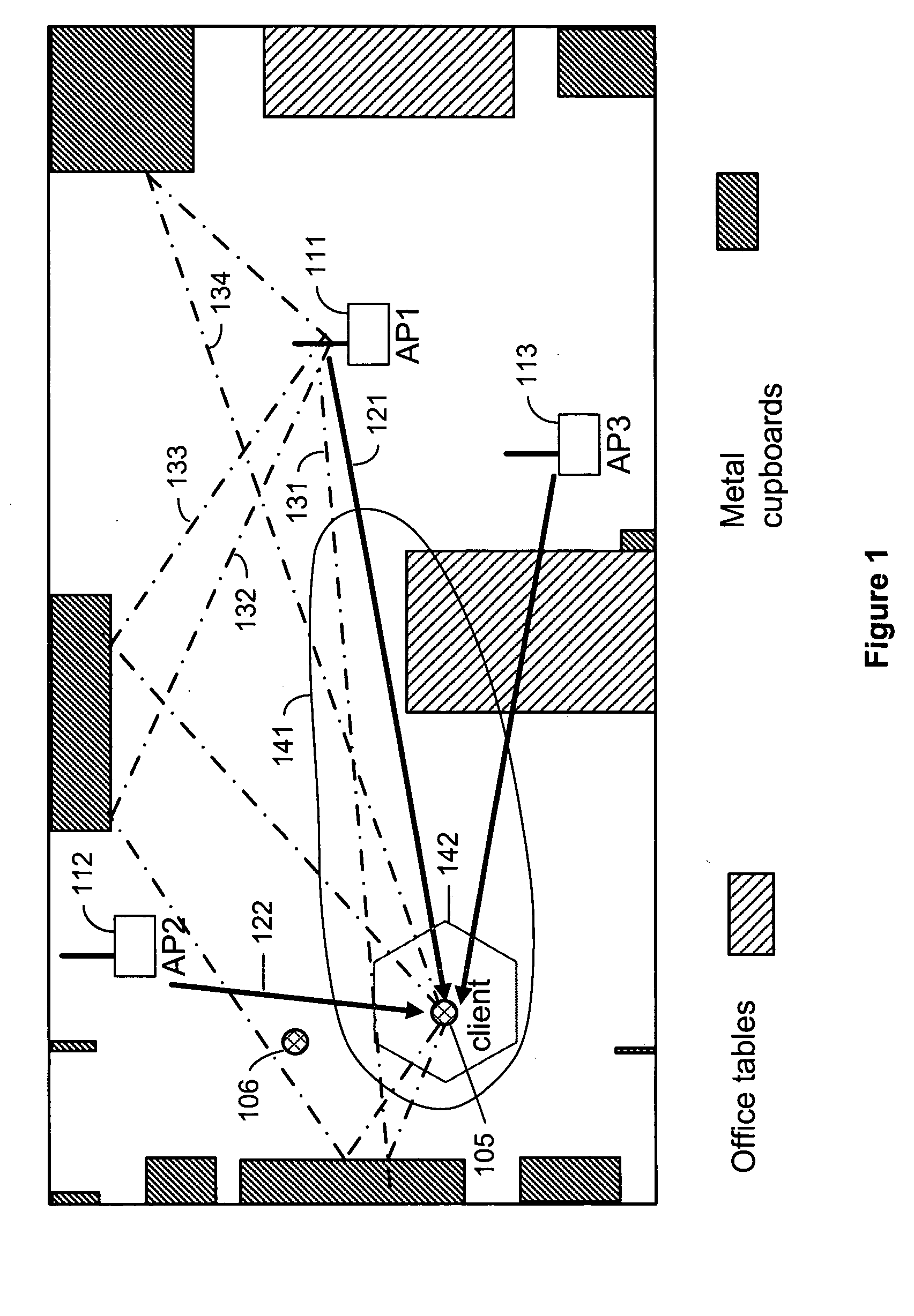
[0012] The indoor environment and complications of obscured line of sight and multipathing are illustrated in FIG. 1. In the figure, the wireless device is labeled “client”105. This wireless device preferably is a WLAN device. Standards for connecting to a WLAN may include 802.11x compliant WLAN technology, line-of-sight microwave and RF access technology, unlicensed 2.4 or 5.25 GHz technology, Bluetooth technology, cellular technology, IS 95b compliant technology, enhanced GSM technology, GPRS technology, Metricom technology, and WMAN technology. It is not practical at this time to use satellite link technology, such as used in some new automobiles, because it ...


PUM


Abstract

The present invention relates to locating a person who is operating a wireless communications device in an indoor environment. In particular, it relates to processing various combinations of RSSI, direction of arrival and flight time characteristics of a signal, as received at two or more and preferably three or more access points. In one embodiment, the access points implement a wireless LAN (WLAN) and the communications device is a telephone operating over the WLAN. In another embodiment, the localization of a wireless device allows a system to reject users who are outside a predefined physical area.

Description

RELATED APPLICATION [0001] This application is related to U.S. patent application Ser. No. 10 / 843,218, “SDMA System Using MU-SIMO for the Uplink and MU-MISO for the Downlink”, by inventor Niels van Erven, filed on 11 May 2004. The related application is incorporated by reference.BACKGROUND OF THE INVENTION [0002] The present invention relates to locating a person who is operating a wireless communications device in an indoor environment. In particular, it relates to processing various combinations of RSSI, direction of arrival and flight time characteristics of a signal, as received at two or more and preferably three or more access points. In one embodiment, the access points implement a wireless LAN (WLAN) and the communications device is a telephone operating over the WLAN. In another embodiment, the localization of a wireless device allows a system to reject users who are outside a predefined physical area. [0003] Strong economic incentives exist for using voice over IP (VOIP) t...

Claims


Application Information

Patent Timeline
Patent Type & Authority Applications(United States)
IPC IPC(8): H04Q7/20H04W64/00
CPCH04W64/00
Inventor DRUMMOND-MURRAY, JUSTINTERRY, ANDREW M.ERVEN, NIELS VANDOGGART, PETER
Owner 3COM
Learn More