
Method and apparatus for packet traversal of a network address translation device

a network address and translation device technology, applied in electrical equipment, digital transmission, data switching networks, etc., can solve the problems of affecting the reception of packets from external computers, affecting the availability of internet protocol (ip) addresses for new assignments, and affecting the ability of internal computers to receive communications (e.g. packets) from external computers

Active Publication Date: 2006-09-28
LOGITECH EURO SA
View PDF47 Cites 46 Cited by
  • Summary
  • Abstract
  • Description
  • Claims
  • Application Information

AI Technical Summary

Problems solved by technology

As the use of the Internet has grown in recent years, available internet protocol (IP) addresses for new assignments are rapidly declining.
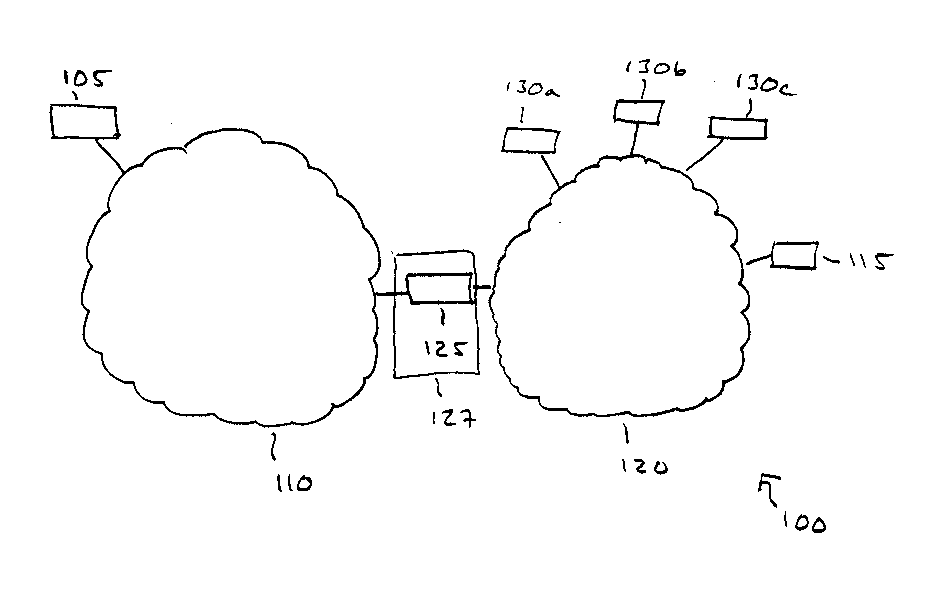
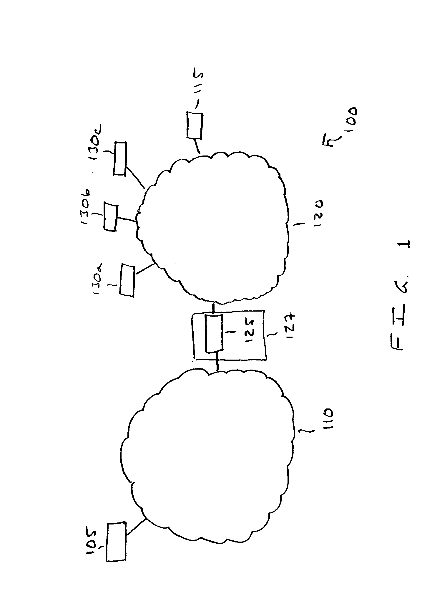
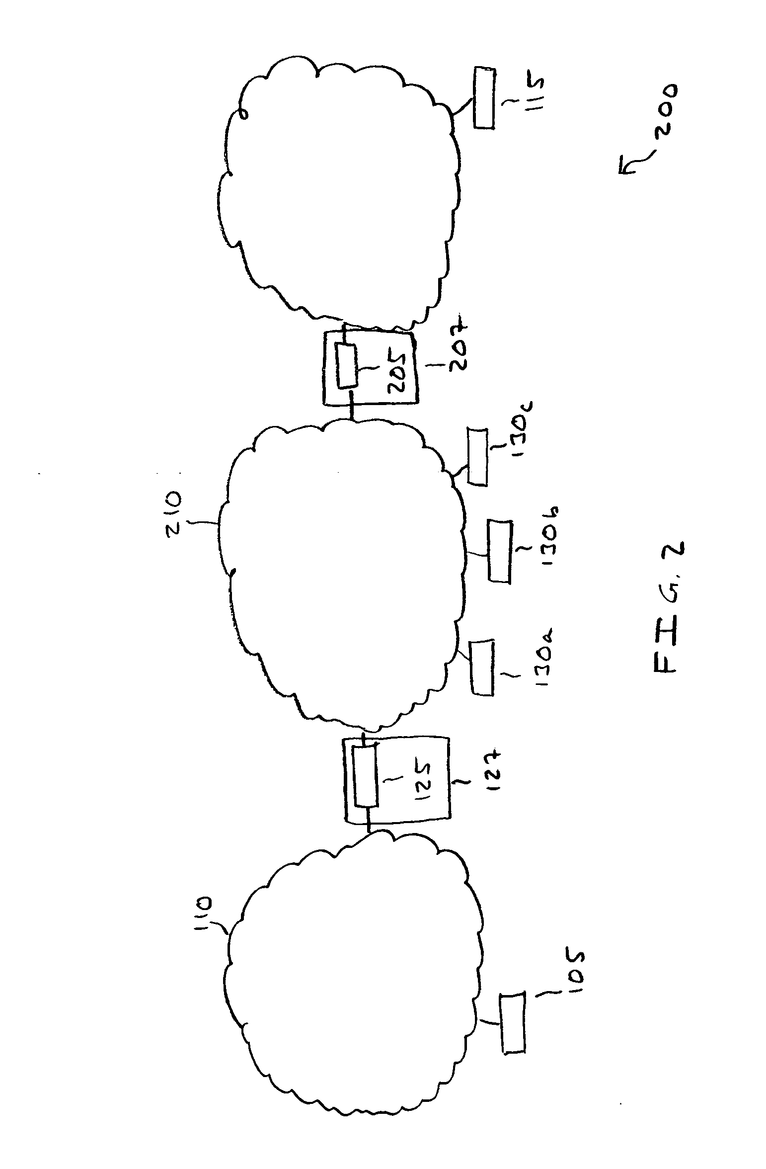
While NAT devices are configured to permit external network connections for a number of internal computers via a single mapped IP address, one or more of these internal computers may not know that they are “behind” a NAT device (i.e., a NAT device is communicatively coupled between the internal computers and external computers) or may not know the characteristics of the NAT device that internal computers are behind.
If an internal computer does not know whether it is behind a NAT device or does not know the characteristics of the NAT device that the internal computer is behind, the internal computer may be hampered in receiving communications (e.g., packets) from external computers.
For example, packets sent to the internal computer from the external computer may be dropped, as the internal computer may not be able to inform the external computer of the characteristics of the NAT device.

Method used


Image

  • Method and apparatus for packet traversal of a network address translation device
  • Method and apparatus for packet traversal of a network address translation device
  • Method and apparatus for packet traversal of a network address translation device

Examples


first embodiment

[0077] According to the port-prediction information, if the internal computer determines that the NAT device does not support UDP packets or other packets used to characterize the NAT device, the internal computer is configured to conclude that a UDP peer-to-peer connection with the external computer is not possible and may be configured to establish another method of communication with the external computer.

second embodiment

[0078] According to the port-prediction information, if the internal computer determined that it is not behind a NAT device and the NAT device is an exceptional NAT device, the internal computer is configured to generate a new socket, say L2, and bind the socket to a random port (e.g., a port between 5000 and 65535). The internal computer then stores the local port number that was bound to socket L2, for example, as L2 port number. Further, the internal computer is configured to set the UDP predicted external port number to the L2 port number as no NAT device is disposed so as to map the L2 port number to a mapped port number. The internal computer is further configured to set the UDP-predicted-internal-port number to the L2 port number.

third embodiment

[0079] According to the port-prediction information, if the internal computer determined that it is not behind a NAT device, and the NAT device is not an exceptional NAT device, then the internal computer is configured to set the UDP-predicted-external-port number to the L1 port number, and is configured to set the UDP-predicted-internal-port number to the L1 port number.


PUM


Abstract

A characterization method for a network address translation (NAT) device by an internal computer behind the NAT device includes creating a plurality of sockets; binding the plurality of sockets, respectively, to a plurality of ports; transmitting a plurality of STUN requests in user datagram protocol (UDP) packets to a plurality of STUN servers, wherein each STUN request is associated with one of the sockets; determining that the NAT device does support UDP packets if responses are not received from the STUN servers; and determining a set of NAT characteristics of the NAT device if a response is received from each of the STUN servers.

Description

BACKGROUND OF THE INVENTION [0001] The present invention relates to communications in computer networks, and more particularly the present invention relates to a system and method for packet traversal of a network address translation device. [0002] As the use of the Internet has grown in recent years, available internet protocol (IP) addresses for new assignments are rapidly declining. More specifically, the number of internet protocol (IP) addresses currently specified by IP version 4 (IPv4) for assignment to new Internet users is rapidly declining. IPv4 specifies the use of four bytes for each IP address. A newer IP version 6 (IPv6) that specifies 16 byte IP addressing has yet to be implemented for Internet use and is not anticipated to be implemented for the next few years. [0003] As IPv6 is not scheduled for use within the next few years, and as available IP addresses are declining, interim solutions have been developed for increasing the number of computers that can connect to ...

Claims


Application Information

Patent Timeline
Patent Type & Authority Applications(United States)
IPC IPC(8): H04L12/56
CPCH04L12/24H04L29/12377H04L29/12528H04L29/12537H04L41/00H04L41/12H04L61/2517H04L61/2575H04L61/2578
Inventor STRANDRIDGE, AARONERBES, KENZIMMERMAN, REMYDEPALLENS, PHILIPPE
Owner LOGITECH EURO SA
Learn More