
Personal protection system

a technology of applied in the direction of application, breathing protection, protective garment, etc., can solve the problems of insufficient air directed toward the neck of the user, inability to provide the most efficient and quietest flow of air possible, and deficiency of conventional personal protection system and helmet assembly, etc., to achieve the effect of effective assembly process

Active Publication Date: 2006-09-28
STRYKER CORP
View PDF95 Cites 64 Cited by
  • Summary
  • Abstract
  • Description
  • Claims
  • Application Information

AI Technical Summary

Benefits of technology

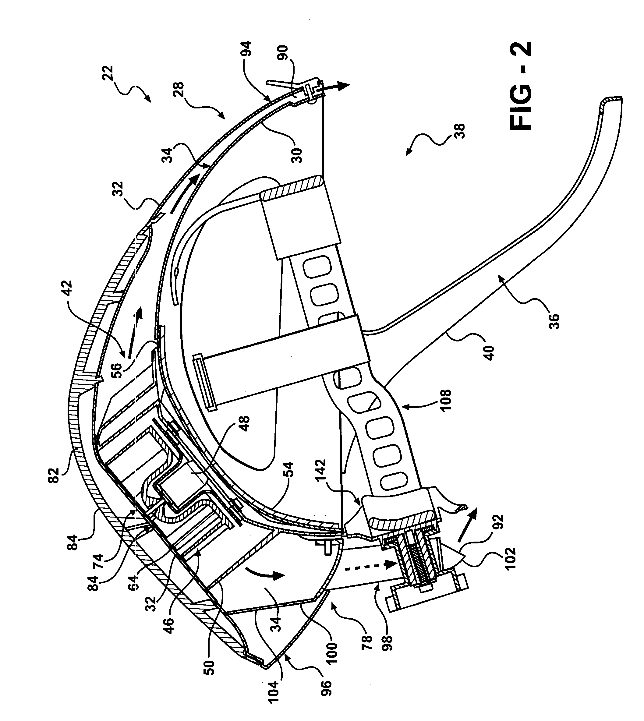
[0011] In a first aspect of the invention, a personal protection unit is disclosed. The personal protection unit includes a support structure for suspending a hood over the head of an individual. A fan module is attached to the support structure, with the fan module receiving air and discharging air. A duct is connected to the support structure and has an opening positioned to receive the air discharged from the fan module. The duct is shaped to have a rear air exit. The duct is arranged relative to the fan module so that only a fraction of the air discharged from the fan module enters the duct. The duct extends from the support structure and the rear air exit is positioned so that air is discharged from the rear air exit directly onto the neck of the individual. By the duct extending from the support structure and discharging air directly on to the neck, the comfort of the individual (e.g., a surgeon) is increased, allowing the individual to focus on the task he or she is performing (e.g., surgery).
[0012] In a second aspect of the invention, the personal protection unit includes the support structure for suspending the hood over the head of the individual. The personal protection unit includes a fan for circulating air. A motor is attached to the support structure and is connected to the fan for actuating the fan. An elastomeric, vibration dampening member holds the motor to the support structure. The vibration dampening member helps to reduce transmission of noise and / or vibrations generated by the fan and / or motor to the user. Reduction of noise and / or vibrations will decrease distractions to the individual.
[0014] A fourth aspect of the invention provides a method of assembling a sterilized hood assembly having a transparent face shield. The method includes the step of providing a hood formed from sterilizable flexible material, a portion of the material being filter material. A transparent face shield assembly is attached to the hood where the shield assembly includes a face shield. The method further includes the step of sterilizing the hood and face shield assembly using a sterilization process that does not adversely affect the filter material. The transparent shield assembly further includes a plurality of removable transparent layers disposed over the face shield. Sterilizing the face shield and removable layers together as a whole provides for a more effective assembly process by negating the possibility of introducing contaminants during subsequent assembly operations.

Problems solved by technology

Conventional personal protection systems and helmet assemblies are deficient for one reason or another.
Thus, the air cannot be directed toward the neck of the user, where most surgeons desire the air's cooling presence.
Other deficiencies of prior art personal protection systems are with the fan assembly.
For instance, the shape of the blades of the fan, which rotate to draw in air, do not provide for the most efficient and quietest flow of air possible.
This causes excessive power consumption, which leads to premature drain of battery packs, and excessive noise, which can be distracting for a surgeon performing delicate operations.
Furthermore, the prior art helmet assemblies tend to transfer vibrations caused by the rotation of the fan to the user, as well as being noisy in general.
The vibrations, as well as the noise, can be distracting to the surgeon, who obviously needs to focus his efforts at the complex task at hand.
Yet another deficiency of the '691 patent concerns the multiple removable layers disposed on the face shield.

Method used


Image

  • Personal protection system
  • Personal protection system
  • Personal protection system

Examples


Embodiment Construction

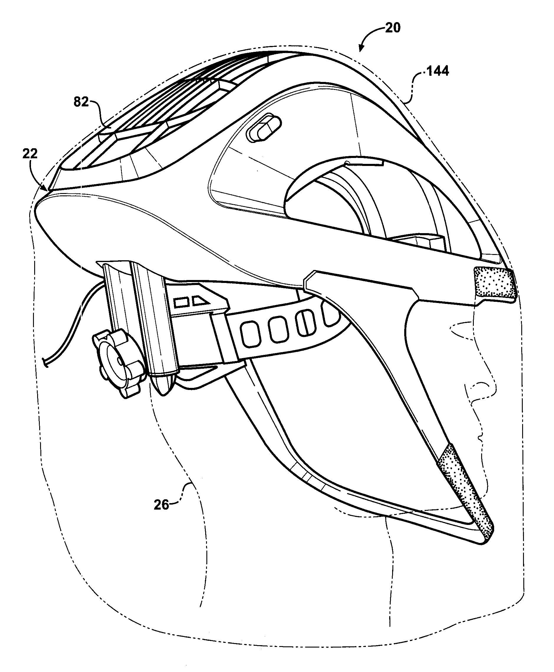
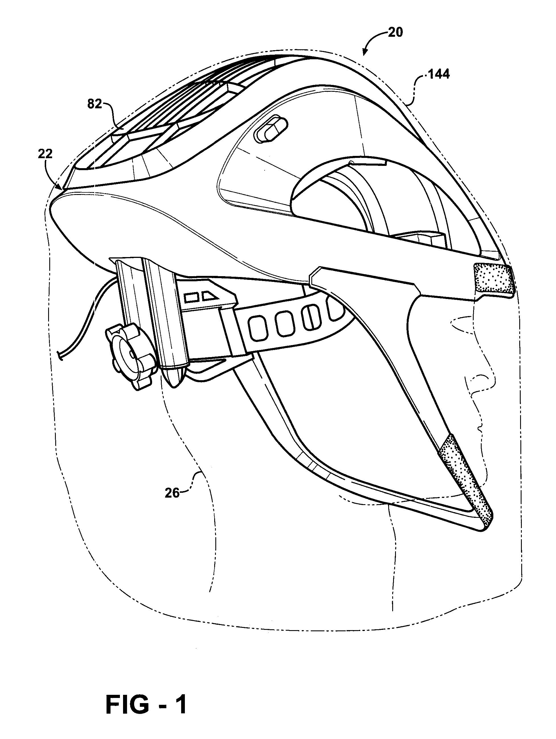
[0031] Referring to the Figures, wherein like numerals indicate corresponding parts throughout the several views, a personal protection system or personal protection unit is generally shown at 20. The personal protection system 20 is mountable to a user (i.e., an individual) for distributing air to the user. The personal protection system 20 of the present invention is adapted from the personal protection systems disclosed in U.S. Pat. No. 6,481,019 to Diaz et al. (the '019 patent) and U.S. Pat. No. 6,973,677 to Diaz et al. (the '677 patent), which are hereby incorporated by reference.

[0032] In the preferred embodiment, as shown in FIG. 1, the personal protection system 20 is implemented as a helmet 22 or helmet assembly 22. The personal protection system 20 filters air between a head 24 and body 26 of a user, e.g., a medical professional, and an environment external to the user. When in use, the preferred helmet assembly 22 of the personal protection system 20 is mounted to the he...


PUM


Abstract

A personal protection system is mountable to a user for distributing air to the user includes a shell providing structure. A fan module is supported by the shell for generating a flow of air. Cushioning is provided between the fan module and the shell to reduce vibrations and noise. The fan module includes a fan with blades having an airfoil shape for added noise reduction. An air flow channel is in fluid communication with the fan module for routing the flow of air. A pair of nozzle tips are in fluid communication with the air flow channel and are rotatably adjustable to allow directional adjustment of the flow of air toward a neck of the user. The personal protection system also includes a face shield with multiple removable layers which are sterilized as a unit using gamma radiation.

Description

CROSS REFERENCE TO RELATED APPLICATION [0001] This application claims the benefit of provisional application Ser. No. 60 / 664,900 filed Mar. 24, 2005, which is hereby incorporated by reference.BACKGROUND OF THE INVENTION [0002] 1. Field of the Invention [0003] The subject invention generally relates to a personal protection system mountable to a user for distributing air to the user. The personal protection system is utilized in the medical profession during surgical procedures. The subject invention more specifically relates to a helmet assembly and gown for use in the personal protection system. [0004] 2. Description of the Prior Art [0005] Personal protection systems and helmet assemblies utilized in personal protection systems are known in the art. As indicated above, personal protection systems and helmet assemblies are worn by users throughout the medical profession, such as surgeons, during surgical procedures. [0006] Conventional personal protection systems and helmet assembl...

Claims


Application Information

Patent Timeline
IPC IPC(8): A61B19/00
CPCA41D13/0025A41D13/11A41D13/1153A42B3/286A61B19/00A62B18/045A61B90/00
Inventor VANDERWOUDE, BRIAN J.HENNIGES, BRUCE D.HUYSER, RICHARD F.PROULX, MARSHALL K.SCLAFANI, ADAM C.BOYLE, DANIEL G.TAGUE, CHRISTOPHER M.STRATTON, DENNIS A.
Owner STRYKER CORP
Learn More