Optical disc drive
- Summary
- Abstract
- Description
- Claims
- Application Information
AI Technical Summary
Benefits of technology
Problems solved by technology
Method used
Image
Examples
first embodiment
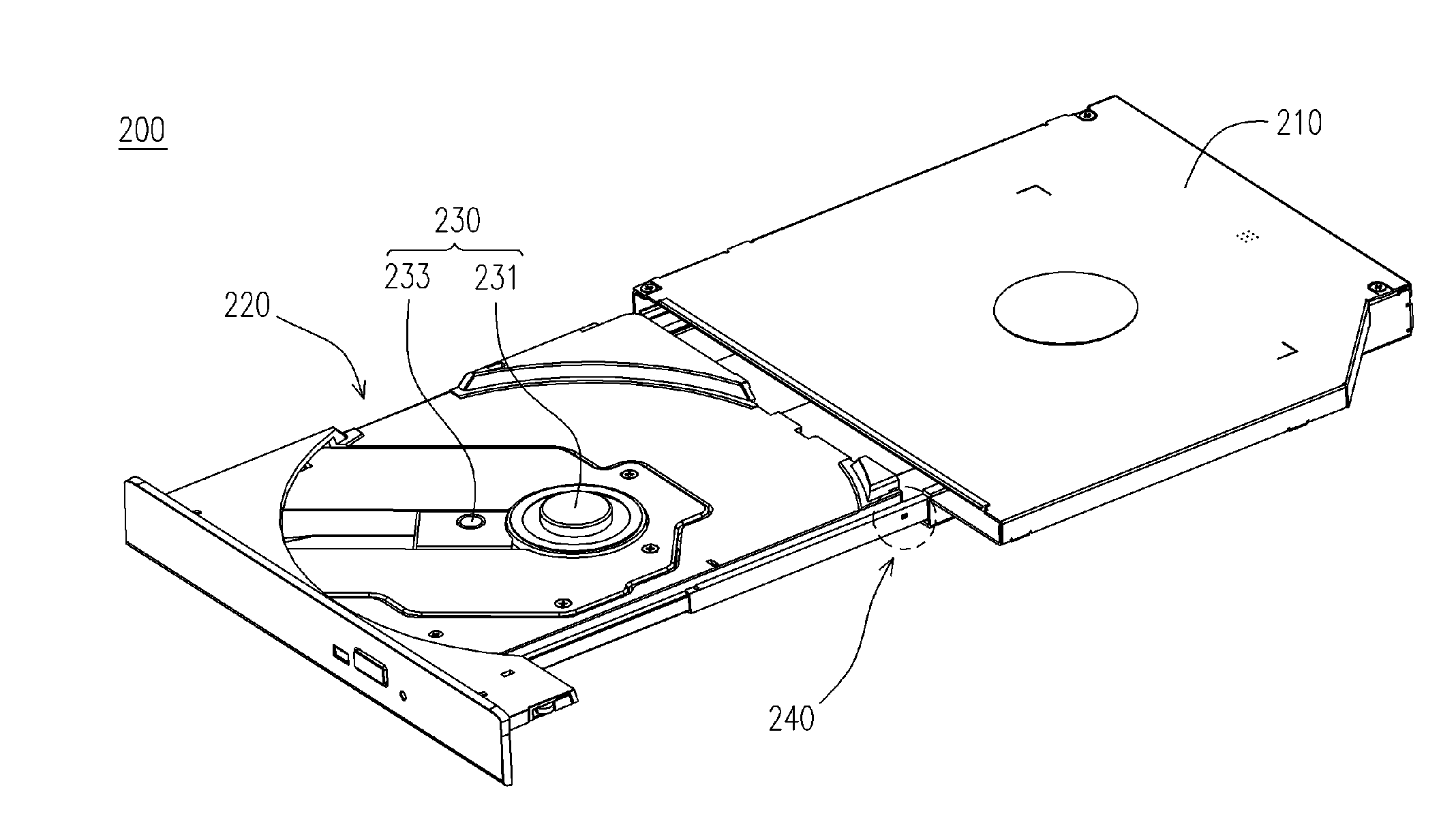
[0030]FIG. 3 is a perspective view of an optical disc drive according to the present invention. FIG. 4 is a perspective view showing the interior of the casing in FIG. 3. FIG. 5 is a locally magnified perspective view showing the tray and the rail in FIG. 3. As shown in FIGS. 3, 4 and 5, an optical disc drive 200 suitable for reading data from an optical disc is provided. The optical disc drive 200 mainly comprises a casing 210, a tray 220, a reading module 230 and a rail 240. The tray 220 is disposed inside the casing 210. The tray 220 has a first positioning part 221 (a protrusion as shown in FIG. 5). Furthermore, the tray 220 is suitable for ejecting from the casing 210. The reading module 230 is disposed on the tray 220 and is suitable for reading data from the optical disc.
[0031] The rail 240 is disposed within the casing 210 and is suitable for withdrawing from the casing 210 when driven by the tray 220. The rail 240 has a second positioning part 241 (a hole in FIG. 5, however...
second embodiment
[0036]FIG. 7 is a top view showing the latching between the first positioning part and the second positioning part in the optical disc drive according to the present invention. As shown in FIG. 7, the first positioning part 321 can be a recess or a hole and the second positioning part 342 can be a protrusion. In addition, the size, location, shape, quantity of the aforementioned recess, hole and protrusion depends on product requirements. Hence, no special restrictions are laid down in these areas in the present invention.
third embodiment
[0037]FIG. 8 is a top view showing the latching between the first positioning part and the second positioning part in the optical disc drive according to the present invention. As shown in FIG. 8, both the first positioning part 421 and the second positioning part 441 are protrusions. Since the size, location, shape, quantity of the aforementioned protrusion depends on product requirements, no special restrictions are laid down in these areas in the present invention.
[0038] As shown in FIGS. 3, 4 and 5, when there is a need to read the data in a particular optical disc, the optical disc is loaded on the tray 220 such that the center of the disc is firmly mounted on the turntable 231. Thereafter, the tray 220 is pushed into the casing 210 guided by the rail 240 such that the elastic first positioning part 221 is disengaged from the second positioning part 241. When the user initiate the reading operation, the turntable 231 will rotate the optical disc and then the optical pick-up 233...
PUM
 Abstract
Description
Claims
Application Information
 - R&D
- Intellectual Property
- Life Sciences
- Materials
- Tech Scout
- Unparalleled Data Quality
- Higher Quality Content
- 60% Fewer Hallucinations
Browse by: Latest US Patents, China's latest patents, Technical Efficacy Thesaurus, Application Domain, Technology Topic, Popular Technical Reports.
© 2025 PatSnap. All rights reserved.Legal|Privacy policy|Modern Slavery Act Transparency Statement|Sitemap|About US| Contact US: help@patsnap.com


