
Bearing for a vacuum roller that can be subjected to suction air from both sides

a vacuum roller and roller body technology, applied in the direction of rolling contact bearings, bearings, shafts and bearings, etc., can solve the problems of no longer having a guarantee that the axial suction air ducts can be subjected uniformly to low pressure over the entire axial extent, subjecting the vacuum roller to low pressure from one side, etc., to achieve the effect of reducing the length of the roller and thus the rotational components

Inactive Publication Date: 2011-03-24
WINKLER DUNNEBIER GMBH
View PDF10 Cites 0 Cited by
  • Summary
  • Abstract
  • Description
  • Claims
  • Application Information

AI Technical Summary

Benefits of technology

[0019]According to one or more embodiments of the present invention, a bearing arrangement for a vacuum roller can be subjected to suction air from both sides, and which ensures, even in the case of thermally caused changes in the length of the roller, an unimpeded rotation of the roller, and also a constant communication of low pressure to the suction air ducts arranged in the roller.
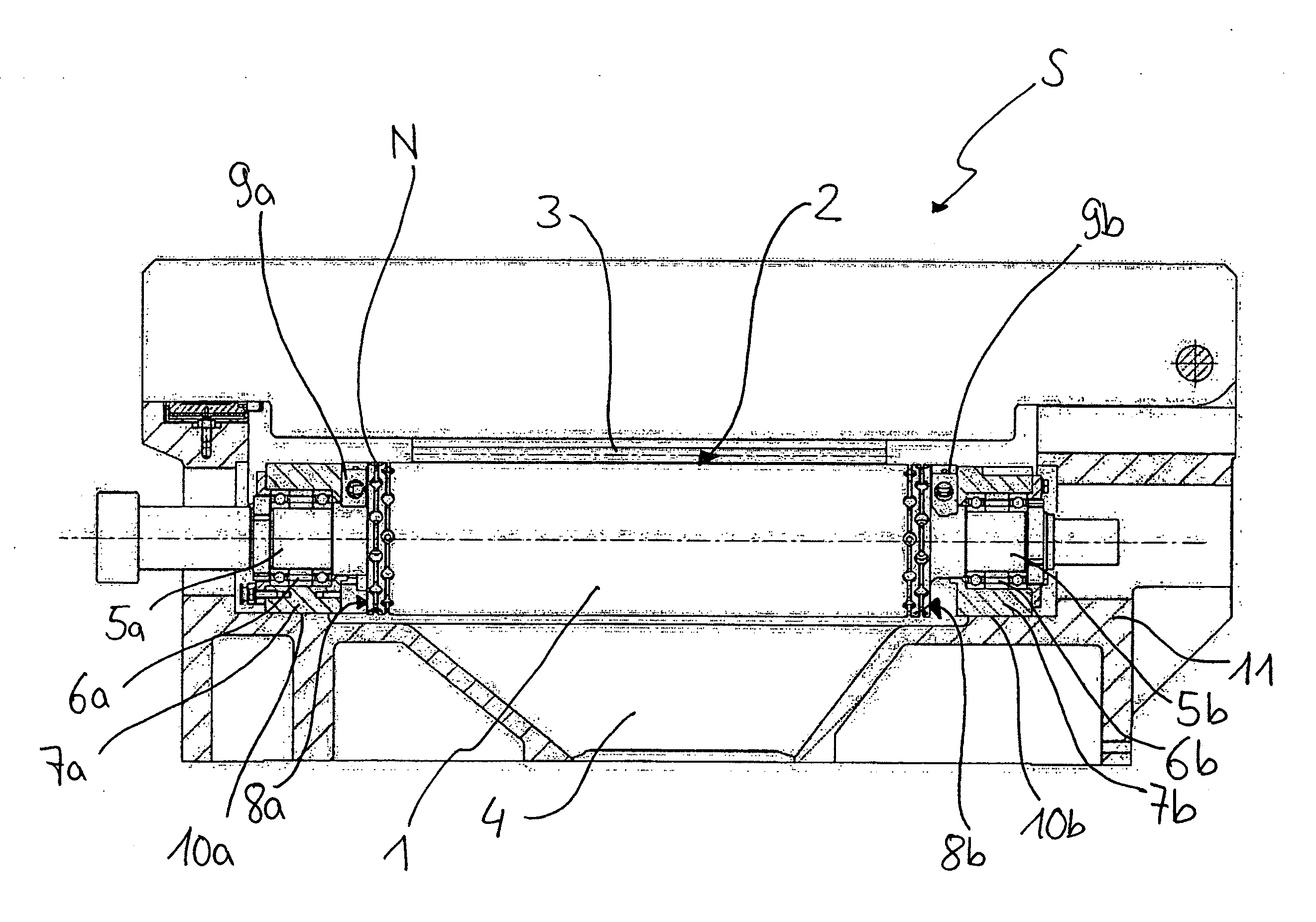
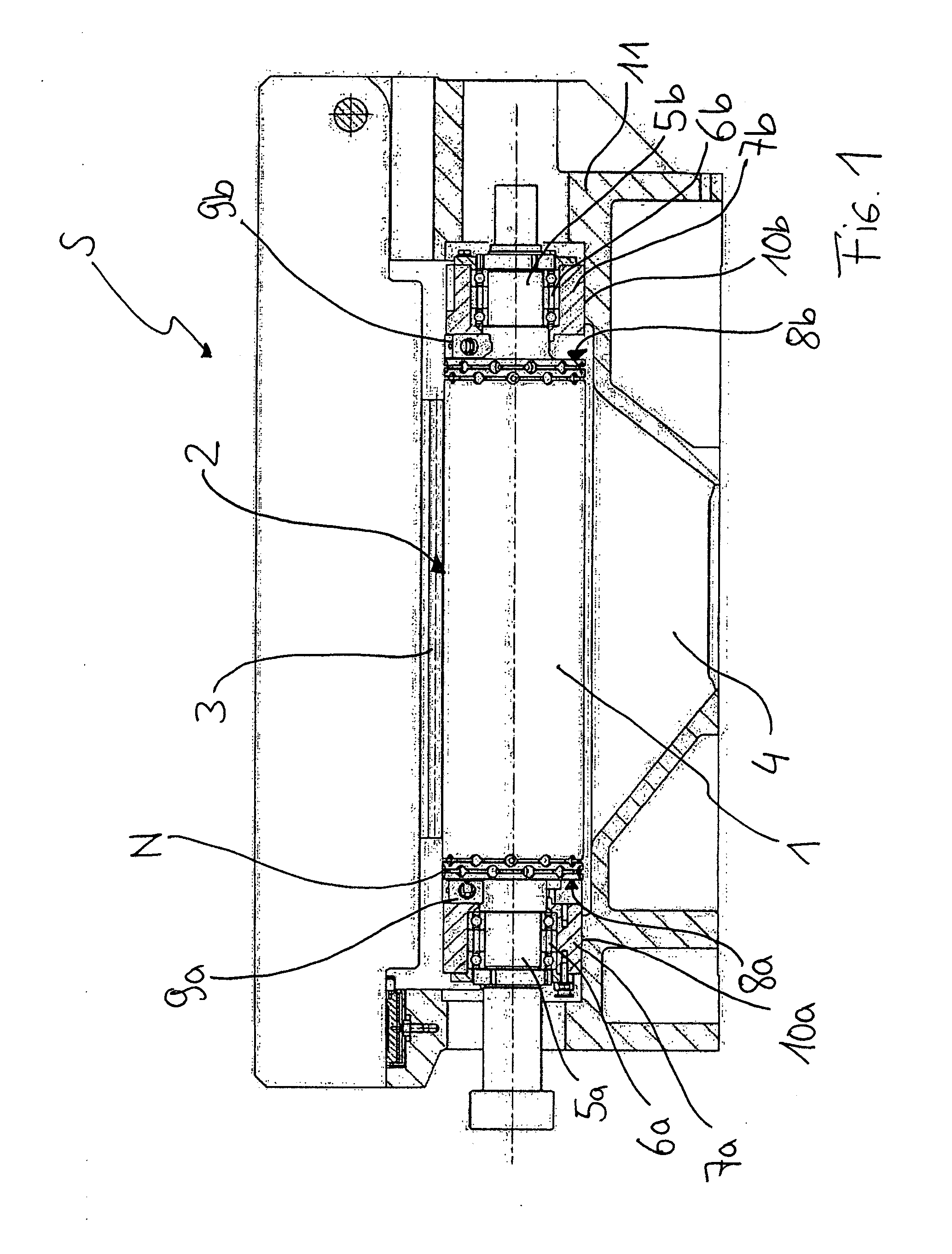
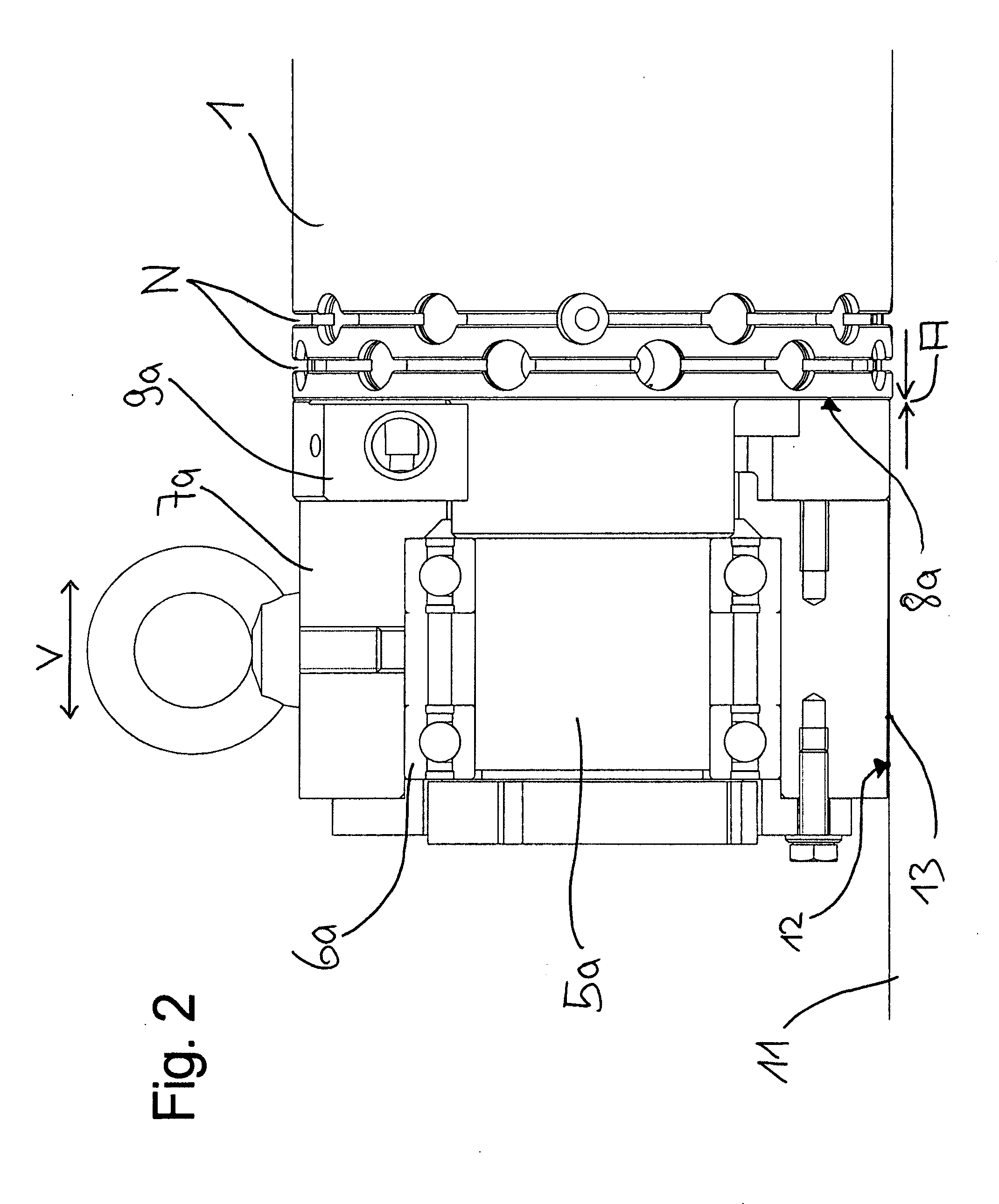
[0021]The roller to be mounted presents at each of its ends a bearing journal, each of which is received by one of the two bearings. According to one or more embodiments of the invention, the roller in both bearings is mounted so it cannot be displaced relative to the respective bearing in the axial direction, so that, on each side of the roller, there is a substantially constant separation between the front face of the roller, which radially surrounds the respective journal, and the stationarely arranged components which face the front face, and which subject the front face of the roller to suction air. The functionality as a floating bearing of the bearing, which is required for a compensation of thermal expansions of the roller body, is achieved according to one or more embodiments of the invention by an arrangement allowing axial displacement of one of the two bearing housings relative to the frame in which the bearing is mounted.
[0032]According to one or more embodiments of the invention, a stationary arrangement of the control disk on the surface of the bearing housing, which faces in each case the front face of the roller, has the advantage that the length of the roller and thus of the rotating components can be reduced, which stabilizes the externally located bearing of the roller.

Problems solved by technology

However, subjecting the vacuum roller to low pressure from one side, as has been done to date, has considerable drawbacks in some applications.
The result of the two above-mentioned points is that, if the vacuum roller is subjected to low pressure from one side, there is no longer any guarantee that the axial suction air ducts can be subjected uniformly to low pressure over the entire axial extent.
However, because of the above-described communication of the low pressure from components that are stationarely arranged to the openings of the suction air ducts, which openings are arranged on the rotating front face, using, on the one hand, a slot sealing, and, on the other hand, the required functionality as a floating bearing of the second bearing because of the thermal length changes of the roller body, in the second bearing, a constant width of the suction slot cannot be maintained.
Thus, in the case of a thermal expansion of the roller body, a contact between the sealing surfaces and jamming of the sealing surfaces can occur, if the chosen slot width is not sufficiently large.
However, once wear of the sealing surfaces has occurred due to expansion, it can no longer be corrected, so that, in the case of thermal changes which result in a shortening of the roller length, the slot presents an undesirably large width, which can lead to increased degradation of the low pressure in the transition from stationary to rotating components, and thus to increased performance requirements for the pump systems or to an unsatisfactory suction effect for the products.

Method used


Image

  • Bearing for a vacuum roller that can be subjected to suction air from both sides
  • Bearing for a vacuum roller that can be subjected to suction air from both sides
  • Bearing for a vacuum roller that can be subjected to suction air from both sides

Examples


Embodiment Construction

[0035]Exemplary embodiments of the invention will be described with reference to the accompanying figures. Like items in the figures are shown with the same reference numbers. In embodiments disclosed herein, numerous specific details are set forth in order to provide a more thorough understanding of the invention. However, it will be apparent to one of ordinary skill in the art that the invention may be practiced without these specific details. In other instances, well-known features have not been described in detail to avoid obscuring the invention.

[0036]FIG. 1 shows a so-called cutting bridge S, as used in a cutting station for manufacturing envelopes. With the vacuum roller 1, which in this case is designed as a knife roller, that is which carries a cutting tool on its lateral surface, the window cutouts of the envelopes are cut out of supplied envelope blanks by means of the cutting tools which rotate in a cutting slot 2 against a fixed cutting bar 3. The cutout window areas ar...


PUM


Abstract

A bearing structure has a frame, a vacuum roller mounted on the frame, operable to be axially subjected to suction air from both sides, a first bearing arranged in a first bearing housing and a second bearing arranged in a second bearing housing, and a first bearing journal disposed on a first end of the roller, and a second bearing journal disposed on a second end of the roller. The roller is mounted in the first bearing so that there is a substantially constant clearance between a first front face of the roller. The roller is mounted in the second bearing so that there is a substantially constant separation between a second front face of the roller. The second bearing housing is arranged such that the second bearing housing is axially displaceable relative to the frame.

Description

FIELD OF THE INVENTION[0001]The invention relates in general to a bearing for a vacuum roller that can be subjected to low pressure and particularly to a bearing for a vacuum roller that can be subjected to low pressure from both sides.BACKGROUND[0002]When transporting flat materials, for example, blanks in the manufacture of envelopes, labels or the like, so-called vacuum rollers are commonly used. These rollers present in their lateral surfaces so-called suction air openings or suction holes which are subjected to low pressure (“suction air”), where the suction action communicated in this way holds the products to be transported on the lateral surface of the vacuum roller.[0003]The suction holes here are in connection with axial suction air ducts running inside the roller, where the suction air ducts open on one of the front faces of the suction roller. A selective application of a low pressure (and / or optionally compressed air) to individual suction air ducts distributed over the...

Claims


Application Information

Patent Timeline
IPC IPC(8): F16C33/46
CPCF16C23/08F16C13/02
Inventor RAUEISER, REINHARD
Owner WINKLER DUNNEBIER GMBH
Learn More