
System and method for tolerating communication lane failures

a communication lane and failure technology, applied in the field of computer systems, can solve problems such as unsatisfactory type of complex error in data segmentation, and the need for elaborate handshaking and/or error correction algorithms

Active Publication Date: 2006-09-21
ORACLE INT CORP
View PDF7 Cites 86 Cited by
  • Summary
  • Abstract
  • Description
  • Claims
  • Application Information

AI Technical Summary

Benefits of technology

"The patent describes a system that can handle communication lane failures. It includes a transmitter and a receiver connected by a communication link with multiple bit lanes. The transmitter sends data, error detection codes, and redundant information to the receiver. Each bit of data is sent sequentially to the receiver through a single-bit lane. The receiver accumulates the data, error detection codes, and redundant information over multiple clock cycles. If there are errors in the data, the receiver can detect them using the error detection codes and then use the redundant information to regenerate the data. The receiver can also determine if the regenerated data is correct using the error detection codes. This system helps to ensure reliable communication even in the event of lane failures."

Problems solved by technology

However, some of the conventional communications mechanisms may require elaborate handshaking and / or error correction algorithms.
In doing so, such systems may rely on some form of transmitter / receiver agreement that a given communication lane has failed.
However, for some systems, this type of complex handshaking and / or error correction may be undesirable.
The receiver may detect an error in the segment of data using the error detecting code.

Method used


Image

  • System and method for tolerating communication lane failures
  • System and method for tolerating communication lane failures
  • System and method for tolerating communication lane failures

Examples


Embodiment Construction

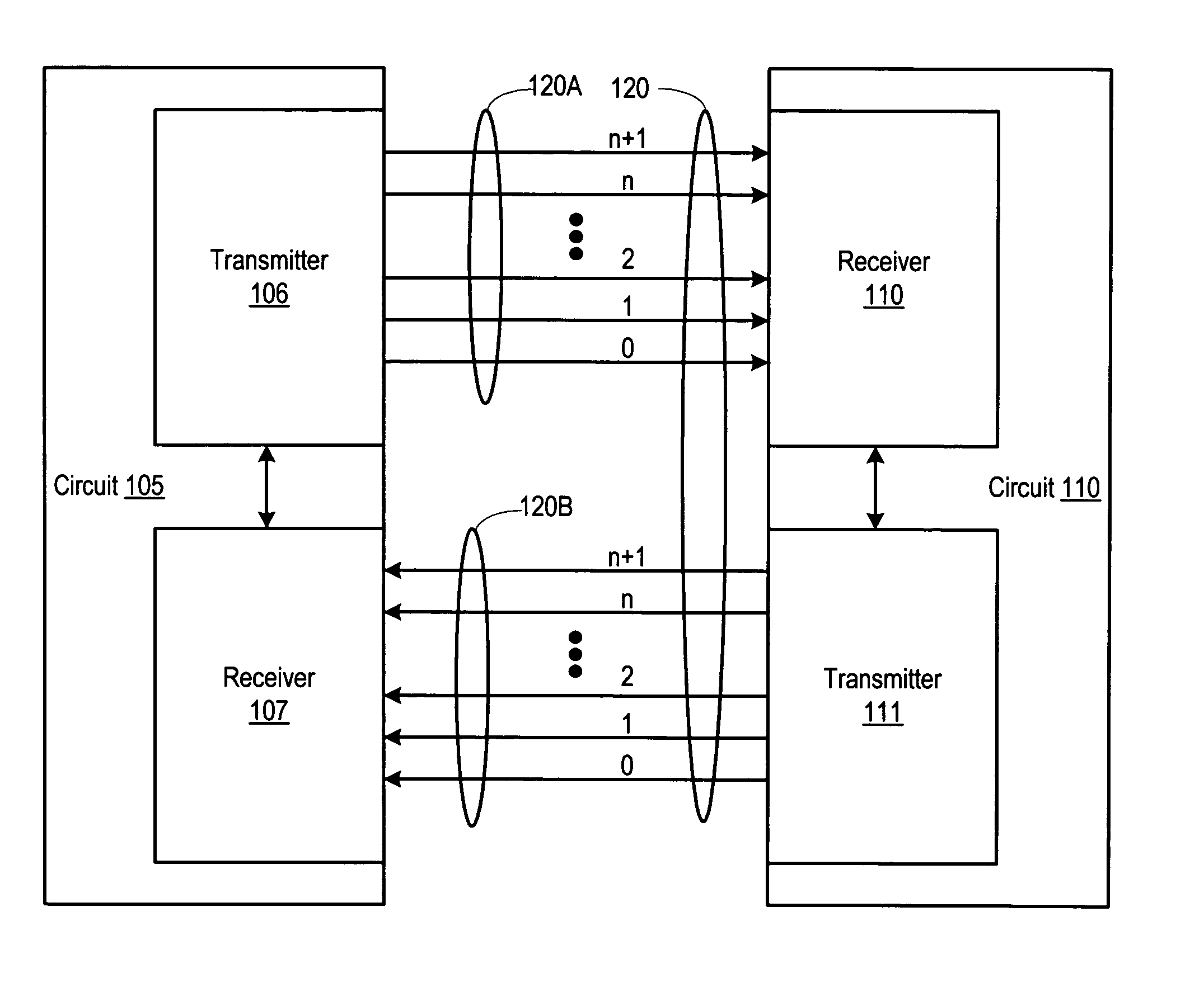
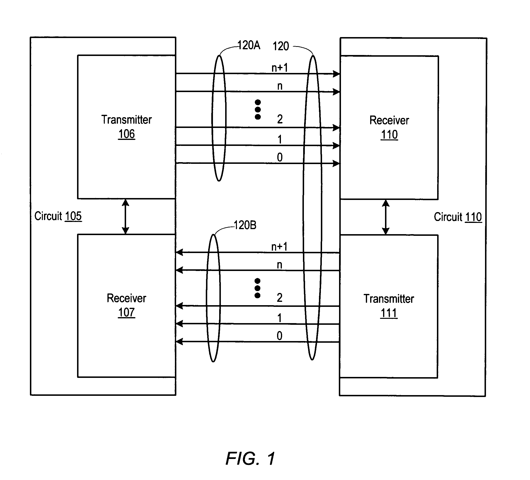
[0011] Turning now to FIG. 1, a diagram depicting one embodiment of two circuits communicating via a bi-directional communication link is shown. Circuit 105 includes a transmitter 106 and a receiver 107. Likewise, circuit 110 also includes a transmitter 111 and a receiver 110. Circuits 105 and 110 are coupled together via a communication link 120. It is noted that circuits 105 and 110 may each be representative of any type of circuit. For example, circuit 105 may be representative of a processor (not shown) while circuit 110 may be representative of an I / O node (not shown) or a memory subsystem (not shown).

[0012] In the illustrated embodiment, communication link 120 includes a pair of unidirectional links 120A and 120B coupled to provide bi-directional communication between circuits 105 and 110. More particularly, transmitter 106 is coupled to receiver 110 via unidirectional link 120A and transmitter 111 is coupled to receiver 107 via unidirectional link 120B. Each of unidirectiona...


PUM


Abstract

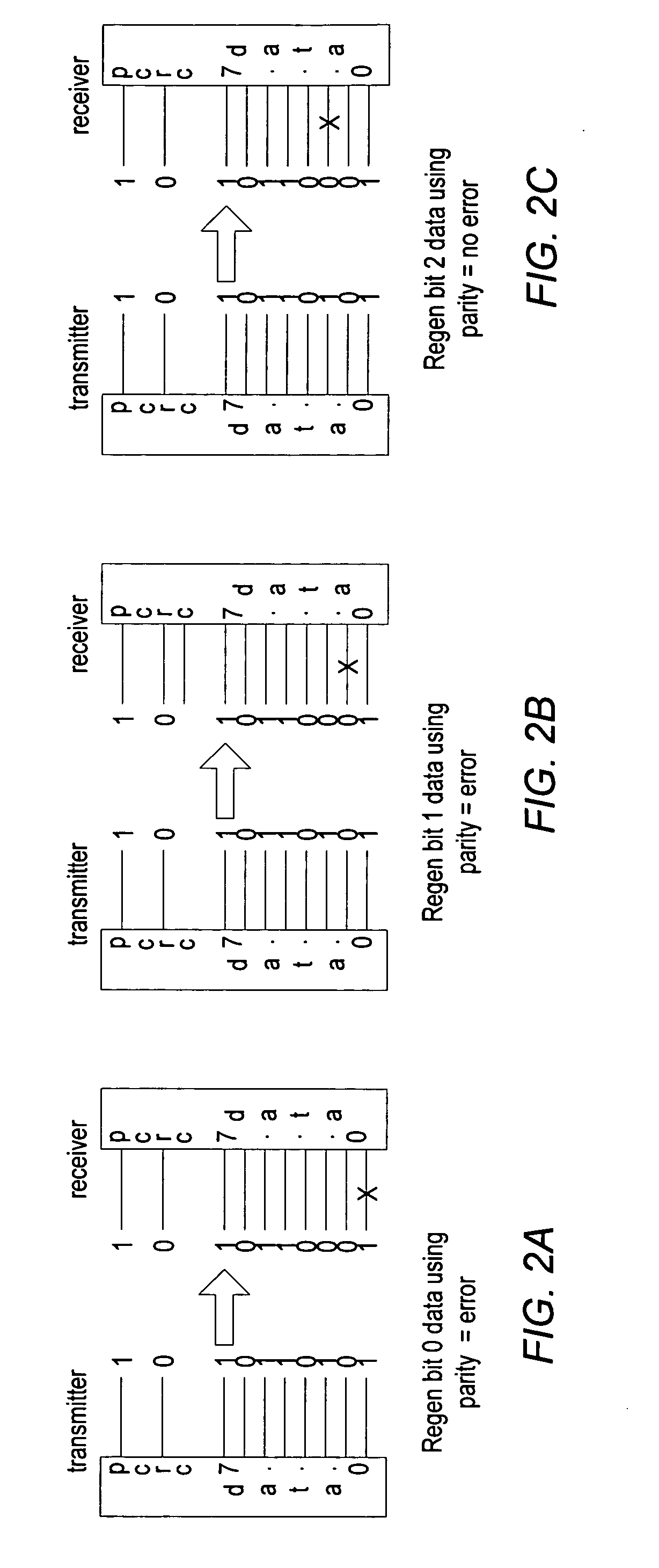
A system for tolerating communication lane failures includes a transmitter configured to transmit a segment of data, an error detecting code, and redundant information. The system also includes a receiver coupled to the transmitter via a communication link including a plurality of bit lanes. Each bit of the segment of data may be conveyed to the receiver serially via respective single-bit lanes. The segment of data, the redundant information, and the error detecting code may be accumulated within the receiver over a plurality of clock cycles. The receiver may detect an error in the segment of data using the error detecting code. In addition, the receiver may, in response to detecting the error, regenerate the segment of data using the redundant information. Further, the receiver may determine whether a resulting regenerated bit, along with remaining bits, of the segment of data are correct using the error detecting code.

Description

BACKGROUND OF THE INVENTION [0001] 1. Field of the Invention [0002] This invention relates generally to computer systems and, more particularly, to error detection and correction in communications between two circuits. [0003] 2. Description of the Related Art [0004] There are many mechanisms for detecting and correcting errors in communications between two devices or circuits. However, some of the conventional communications mechanisms may require elaborate handshaking and / or error correction algorithms. For example, some systems that employ multiple parallel communication lanes to convey information between two circuits may communicate error detection / correction information back to the sending device upon detection of an error. In doing so, such systems may rely on some form of transmitter / receiver agreement that a given communication lane has failed. However, for some systems, this type of complex handshaking and / or error correction may be undesirable. SUMMARY [0005] Various embod...

Claims


Application Information

Patent Timeline
Patent Type & Authority Applications(United States)
IPC IPC(8): H03M13/00
CPCH03M13/09H04L1/0045H04L1/0057H04L1/0063H04L1/18H04L25/14
Inventor CYPHER, ROBERT E.
Owner ORACLE INT CORP
Learn More