
Bluetooth tire pressure monitor system

a tire pressure monitor and bluetooth technology, applied in the direction of tire measurement, vehicle components, transportation and packaging, etc., can solve the problems of difficult and many traffic accidents, and achieve the effects of reducing fuel costs, reducing vehicle accident rates, and increasing tire li

Inactive Publication Date: 2006-09-21
QUACH TUAN +2
View PDF12 Cites 45 Cited by
  • Summary
  • Abstract
  • Description
  • Claims
  • Application Information

AI Technical Summary

Benefits of technology

[0006] Accordingly, it is the general purpose and object of the present invention to provide a vehicle tire pressure monitor system with basic tire pressure warning functionality and convenience in installation, convenience in use and convenience in maintenance. By monitoring and controlling air pressure within the tire at proper values, the goals of increased tire lifetime, reduced fuel cost and lower vehicle accident rates caused by flat tires and fire can be achieved. The present invention is suitable for all vehicles having from four to twelve tires; and systems may be combined for extension purpose.

Problems solved by technology

Those many running vehicles cause numerous traffic accidents.
For after-market assembly, existing motor vehicles, it is not easy.

Method used


Image

  • Bluetooth tire pressure monitor system
  • Bluetooth tire pressure monitor system
  • Bluetooth tire pressure monitor system

Examples


Embodiment Construction

[0021] The following detailed description is of the best modes of carrying out the invention. The description is not to be taken in a limiting sense, but is made merely for the purpose of illustrating the general principles of the invention, since the scope of the invention is best defined by the appended claims.

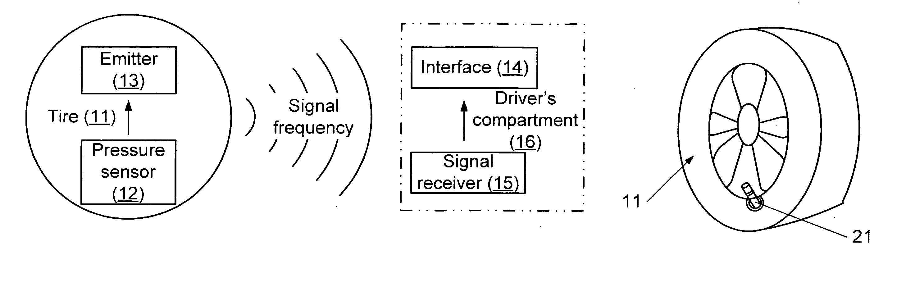
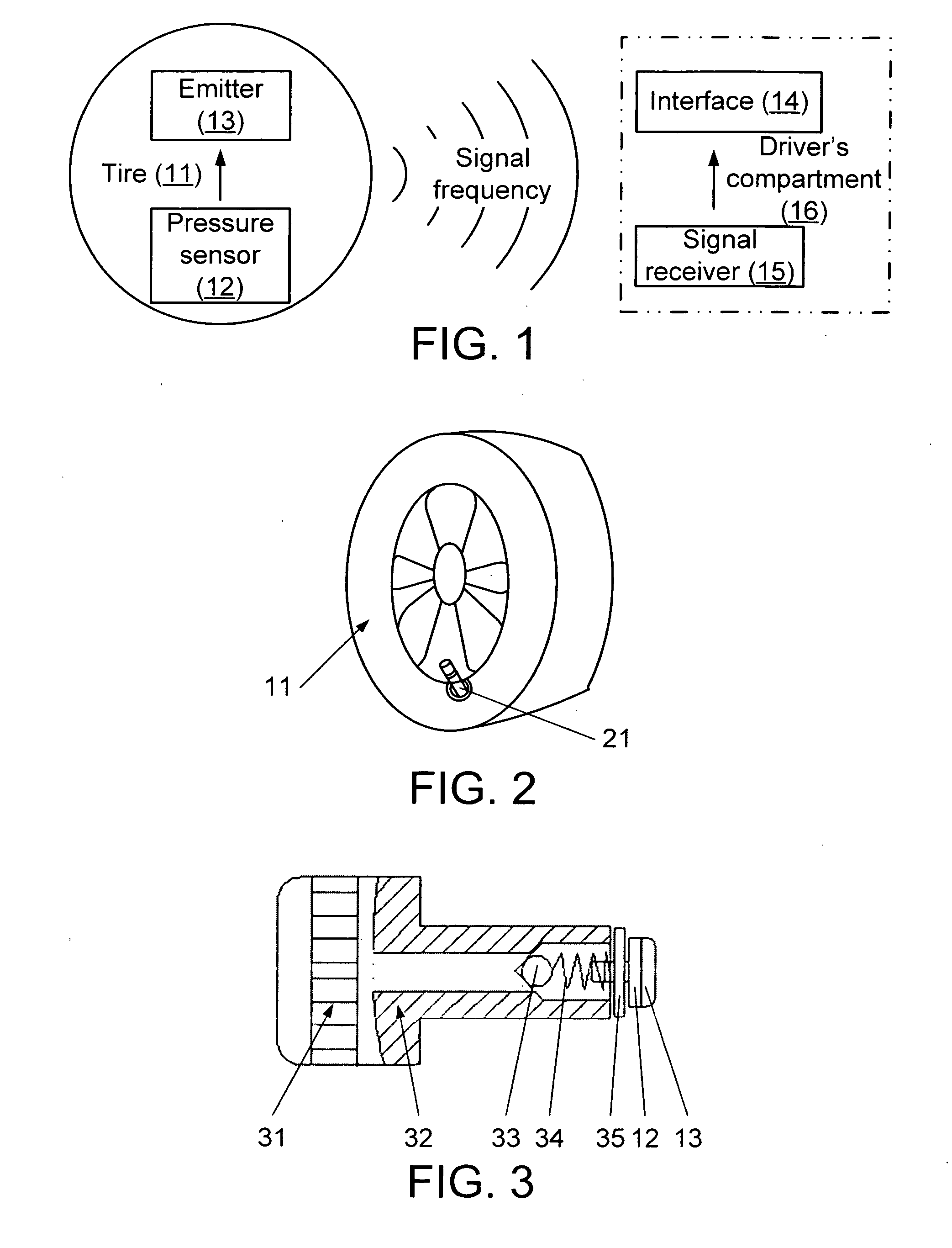
[0022] With reference to the drawings, FIG. 1 illustrates the control principle of the preferred embodiment of the invention, a Bluetooth Tire Pressure Monitor System 10. The system 10 includes a pressure sensor 12, a signal emitter 13, a user interface 14 and a signal receiver 15. The pressure sensor 12 and the signal emitter 13 are integrated with an inflating valve 21 (see FIG. 3) which installed within tire 11, and the user interface 14 and the signal receiver 15 are situated in the driver's compartment 16, usually on the dasboard.

[0023] The pressure sensor 12 measures the air pressure within the tire 11. According to Bluetooth wireless control principles, two control ...


PUM


Abstract

The Bluetooth tire pressure monitor system (10) is provided to mount on the various tires (11) of a vehicle, The system (10) includes a pressure sensor (12), a signal emitter (13), a display screen (14) and a signal receiver (15). The pressure sensor (12) and emitter (13) are integrated with a customized inflating valve (21) and installed in the tire (11). The signal receiver (15) and display screen / user interface (14) are placed in the driver's compartment (16) of the vehicle in a highly visible location, usually on the dashboard. The pressure sensor (12) senses the pressure in the tire (11). The signal emitter (13) collects and converts the pressure signal from the pressure sensor (12) and transmits the signal wirelessly (using the Bluetooth protocol) to signal receiver (15) which converts the signal and delivers it to the user interface / display screen (14) which displays the signal. The signal receiver (15) and display screen (14) are shared components, signal receiver (15) distinguishes and identifies all frequencies (50) from the associated signal emitter (13) of each tire (11) first, then addresses the signals to the matching tire of display screen (14). The display screen (14), usually in the from of an adhesively attached film-shape, indicates the position and pressure condition of all tires. The condition is preferably shown in red, yellow and green colors based on the air pressure range. When the range is 76-100%, the indicating light is green (38), when the range is 50-75%, the indicating light is yellow (39) and when it is lower than 50%, indicating light is red (40. The inflating valve (21) of the Bluetooth Tire Pressure Monitor System (10), includes a valve cap 31, a valve rod 32, a single direction valve 33, a spring 34, a support 35, the pressure sensor 12 and the emitter 13, along with a battery 36 to power the sensor and emitter.

Description

[0001] The following claims priority from a provisional patent application 60 / 522,987, filed 30 Nov. 2004 to one of the same inventors.BACKGROUND OF THE INVENTION [0002] The present invention relates to motor vehicle safety field, and more particularly to a vehicle Bluetooth Tire Pressure Monitor System. It pertains to all new motor vehicles' development and existing motor vehicles. [0003] Recent decade, accompanying automobile's development, more and more vehicles are running on the road. Three hundred twenty million motor vehicles registered in United States in year 2004 only. Those many running vehicles cause numerous traffic accidents. It is big percentage that because of flat tire and fire. According to statistics, the lifetime of the tire may reduce to 50% and fuel cost may increase up to 30% because of improper tire pressure. [0004] In some developed countries, from government to consumers, people have paid much attention on this issue. As a result of recent legislation of US...

Claims


Application Information

Patent Timeline
Patent Type & Authority Applications(United States)
IPC IPC(8): B60C23/00B60C23/02
CPCB60C23/007B60C23/009B60C23/0401B60C23/0408
Inventor QUACH, TUANQUACH, TONYGUO, YANXIA
Owner QUACH TUAN
Learn More