Low vibration tube

a technology of low vibration and suction tube, which is applied in the field of medical devices, can solve the problems of vibration of the suction tube, the risk of bruising, swelling and discomfort accompanying surgery, and the vacuuming of unwanted fa

Inactive Publication Date: 2006-09-14
MICROAIRE SURGICAL INSTR
View PDF6 Cites 4 Cited by
  • Summary
  • Abstract
  • Description
  • Claims
  • Application Information

AI Technical Summary

Benefits of technology

[0008] It is therefore an object of the present invention to provide a way to isolate the vibration...

Problems solved by technology

Guided by the surgeon, the suction device literally vacuums away unwanted fat.
In traditional lipoplasty, a risk of bruising, swelling and discomfort can accompany the surgery because the surgeon is required to use his/her own strength to move the cannula back and forth.
One of the issues with a Power Assisted Lipoplasty (PAL) instru...

Method used


Image

  • Low vibration tube
  • Low vibration tube
  • Low vibration tube

Examples


Embodiment Construction

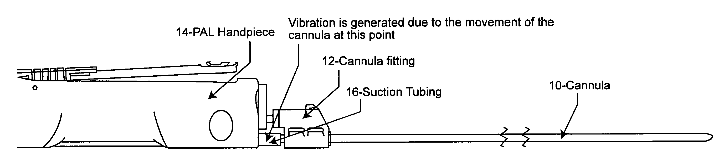
[0015] Referring now to the drawings, and more particularly to FIG. 1, there is shown in schematic diagram form the connection of the cannula, handpiece and tubing of a conventional PAL instrument. More particularly, the cannula 10, which is reciprocated by an electrical or pneumatic power source (not shown), is held by a cannula fitting 12 which facilitates attachment to a handpiece 14. The cannula 10 is attached to suction tubing 16 which is connected to a vacuum container. The suction tubing 16, typically made of polyvinyl chloride (PVC), passes through the handpiece 14 but is not attached to the handpiece. An example of this type of PAL instrument is the Power Assisted Lipoplasty devices manufactured and sold by MicroAire® Surgical Instruments of Charlottesville, Va. The MicroAire® Power Assisted Lipoplasty device uses a 2 mm reciprocating movement at 4000 cycles per minute to facilitate the movement of the cannula in tissue.

[0016] In use, the surgeon typically holds the handpi...


PUM


Abstract

Energy absorption tubing is provided between the cannula and the suction tubing connected to a vacuum in a Power Assisted Lipoplasty device. The energy absorption tubing isolates the vibration or keeps the motion away from the handpiece, making the handpiece more comfortable to hold for the surgeon.

Description

PRIORITY INFORMATION[0001] This application claims priority to provisional application Ser. No. 60 / 661,014 filed Mar. 14, 2005.BACKGROUND OF THE INVENTION [0002] 1. Field of the Invention [0003] The present invention generally relates to medical devices and, more particularly, to improvements in a Power Assisted Lipoplasty (PAL) instrument. [0004] 2. Background Description [0005] Lipoplasty is a surgical procedure in which fat is removed by first inserting a small, hollow tube, called a cannula, through one or more tiny incisions near an area to be suctioned. The cannula is connected by tubing to a vacuum. Guided by the surgeon, the suction device literally vacuums away unwanted fat. [0006] Power Assisted Lipoplasty (PAL) is a technique for liposuction approved by the FDA in December of 1998. With Power Assisted Lipoplasty, the cannula is powered by gas or electricity. The cannula is able to power through tissue and vacuum out the fat and fibrous or scared tissue with less effort th...

Claims


Application Information

Patent Timeline
IPC IPC(8): A61M1/00
CPCA61B17/22004A61M1/0039A61M2202/08A61M2202/0014A61M1/76
Inventor FARD, MIKE
Owner MICROAIRE SURGICAL INSTR
Why Eureka
Try Eureka