[0011] However, objects of these cylindrical illumination devices are, respectively, to be abler to clearly see an image from any angle, to provide a large sized display screen that is light-weight and bright, to illuminate a wide illumination area with high brilliance, and to enable improvement of color effects (glittering
sensation), but not to make a presentation using light from a light source, a light emitting element, or an illuminating lamp.
[0016] Furthermore, in a second aspect of the present invention as described in the first aspect, the cylindrical illumination device (for example, the illumination device 7) includes an optical shield (for example, the optical shield 221) for blocking light from the various light emitting members (for example, the
full color LEDs 222) by being placed inside the transparent member (for example, the transparent member 223), and by an area radiated by light from the plurality of light emitting members (for example, the
full color LEDs 222) on an inner face of the transparent member (for example, the transparent member 223) being restricted by the optical shield (for example, the optical shield 221), the light that is emitted from the plurality of light emitting members (for example, the
full color LEDs 222), after passing through the transparent member (for example, the transparent member 223), is prevented from returning again inside the transparent member (for example, the transparent member 223). DETAILED DESCRIPTION OF THE INVENTION
[0019] Moreover, in a fourth aspect of the present invention as described in the third aspect, in the
game machine (for example, the
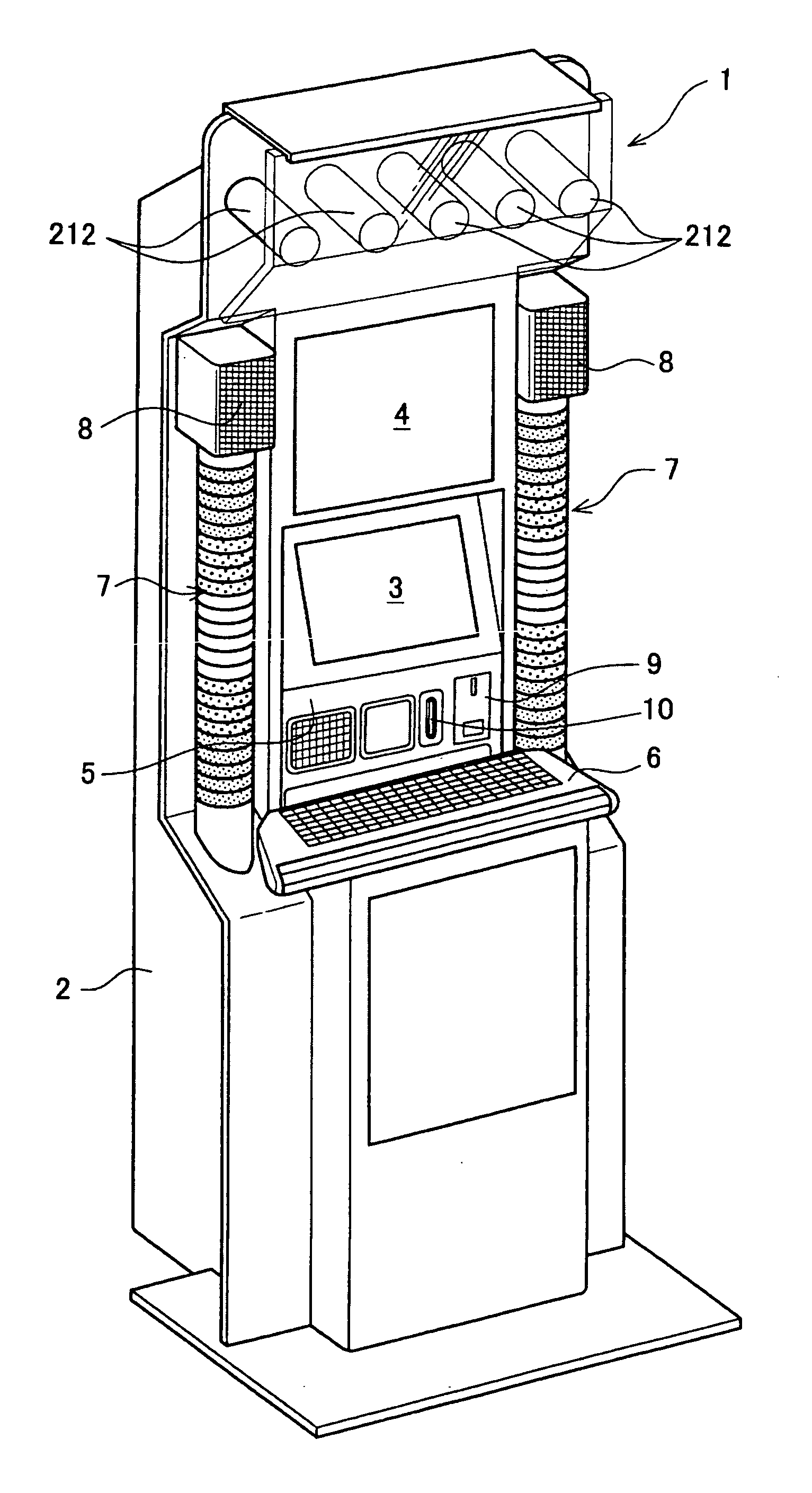
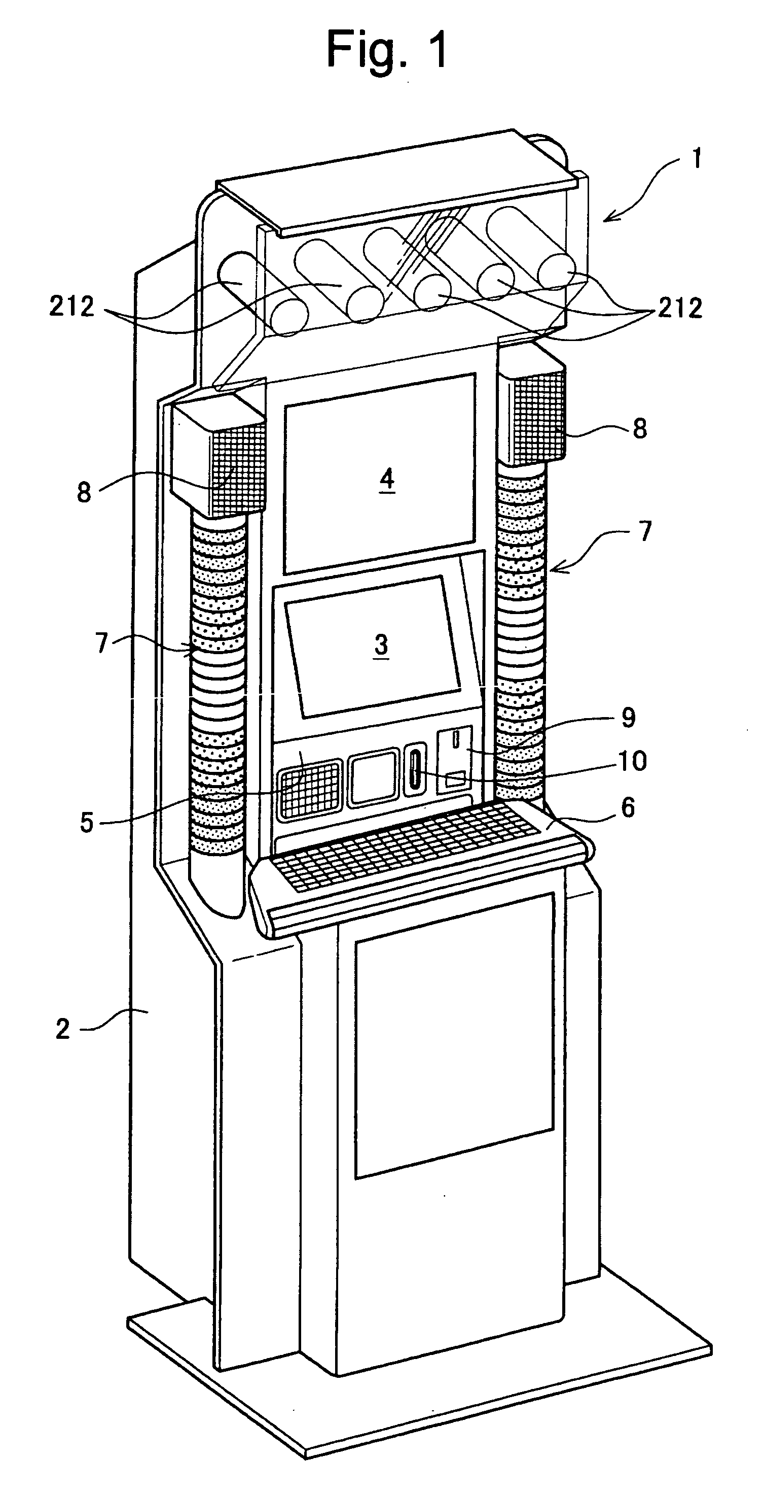
typing game machine 1), the cylindrical illumination device (for example, the illumination device 7) includes the transparent member (for example, the transparent member 223) in which the
lenticular lens of cylindrical shape is arranged in a longitudinal direction, and the light emitting members (for example, the full color LEDs 222) are disposed in a vertical direction at prescribed intervals inside the transparent member (for example, the transparent member 223), and a visual illusion of the existence of light emitting rings, respectively arrayed in a horizontal direction and respectively disposed in a vertical direction inside the transparent member (for example, the transparent member 223), is created by light emitted from the plurality of light emitting members (for example, the full color LEDs 222).
[0020] In addition, in a fifth aspect of the present invention as described in the fourth aspect, in the game
machine (for example, the
typing game
machine 1), the cylindrical illumination device (for example, the illumination device 7) includes the optical shield (for example, the optical shield 221) for blocking light from the plurality of light emitting members (for example, the full color LEDs 222) by being placed inside the transparent member (for example, the transparent member 223), and, by the optical shield (for example, the optical shield 221) restricting the area radiated by the light from the plurality of light emitting members (for example, the full color LEDs 222) on an inner face of the transparent member (for example, the transparent member 223), the light that is emitted from the plurality of light emitting members (for example, the full color LEDs 222), after passing through the transparent member (for example, the transparent member 223), is prevented from returning again inside the transparent member (for example, the transparent member 223).
[0023] In addition, in an eighth aspect of the present invention as described in the seventh aspect, in the game
machine (for example, the
typing game machine 1), the cylindrical illumination device (for example, the illumination device 7) includes the optical shield (for example, the optical shield 221) for blocking light from the plurality of light emitting members (for example, the full color)LEDs 222) by being placed inside the transparent member (for example, the transparent member 223), and, by the optical shield (for example, the optical shield 221) restricting the area radiated by the light from the plurality of light emitting members (for example, the full color LEDs 222) on the inner face of the transparent member (for example, the transparent member 223), the light that is emitted from the plurality of light emitting members (for example, the full color LEDs 222), after passing through the transparent member (for example, the transparent member 223), is prevented from returning again to inside the transparent member (for example, the transparent member 223).
[0024] That is, in the cylindrical illumination device of the present invention, by the positional relationship of the cylindrical transparent member that is the lenticular lens, and the plurality of light emitting members inside the transparent member, when the light is emitted by the plurality of light emitting members, the visual illusion of the existence of the light emitting rings, respectively arrayed in a horizontal direction and respectively disposed in a vertical direction inside the cylindrical transparent member, can be created, and since a presentation in stages, by the light emitting rings, is possible, a new illumination presentation can be performed.


