
Method for making a stressed structure designed to be dissociated

a stress structure and stress technology, applied in the direction of basic electric elements, semiconductor/solid-state device manufacturing, electric apparatus, etc., can solve the problems of high internal stress, damage to the structure, and damage to at least one of these two structures

Inactive Publication Date: 2006-09-14
COMMISSARIAT A LENERGIE ATOMIQUE ET AUX ENERGIES ALTERNATIVES
View PDF59 Cites 24 Cited by
  • Summary
  • Abstract
  • Description
  • Claims
  • Application Information

AI Technical Summary

Benefits of technology

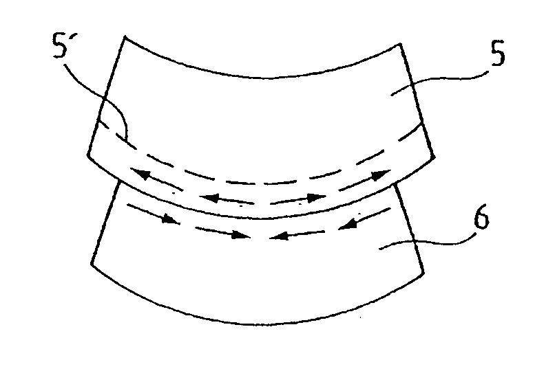
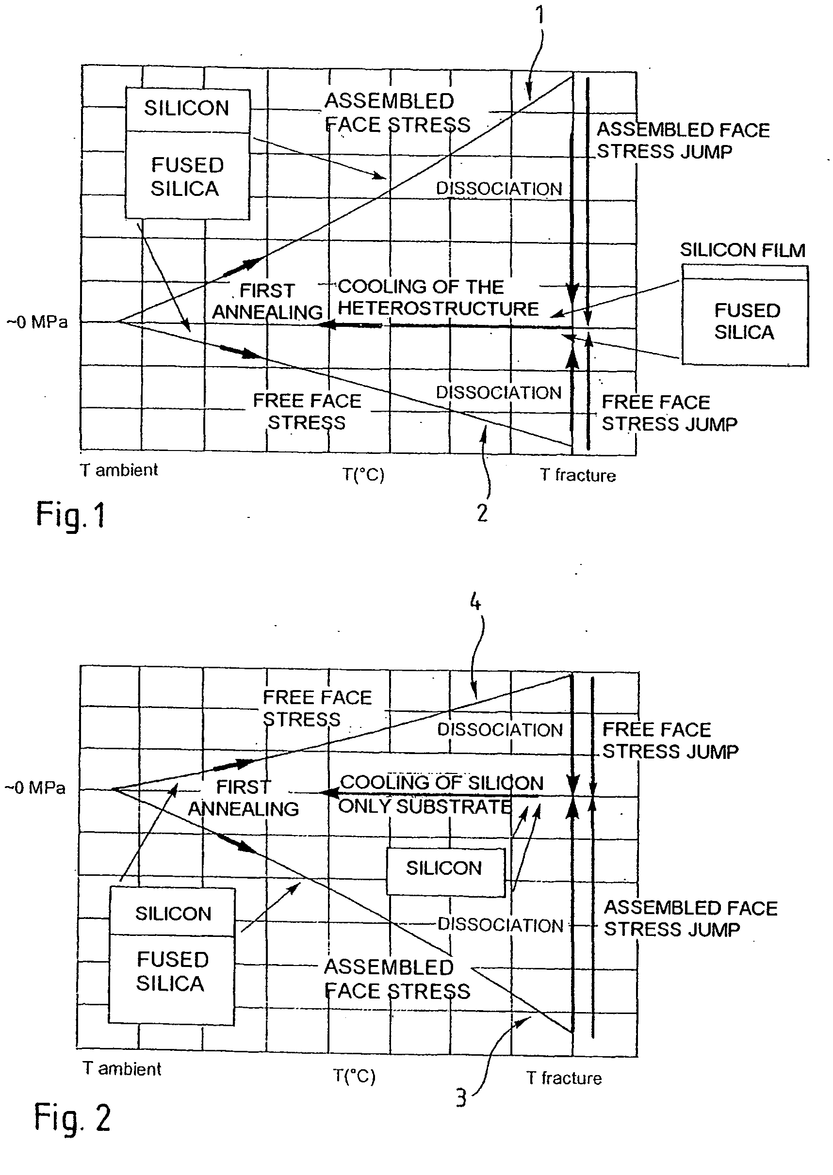
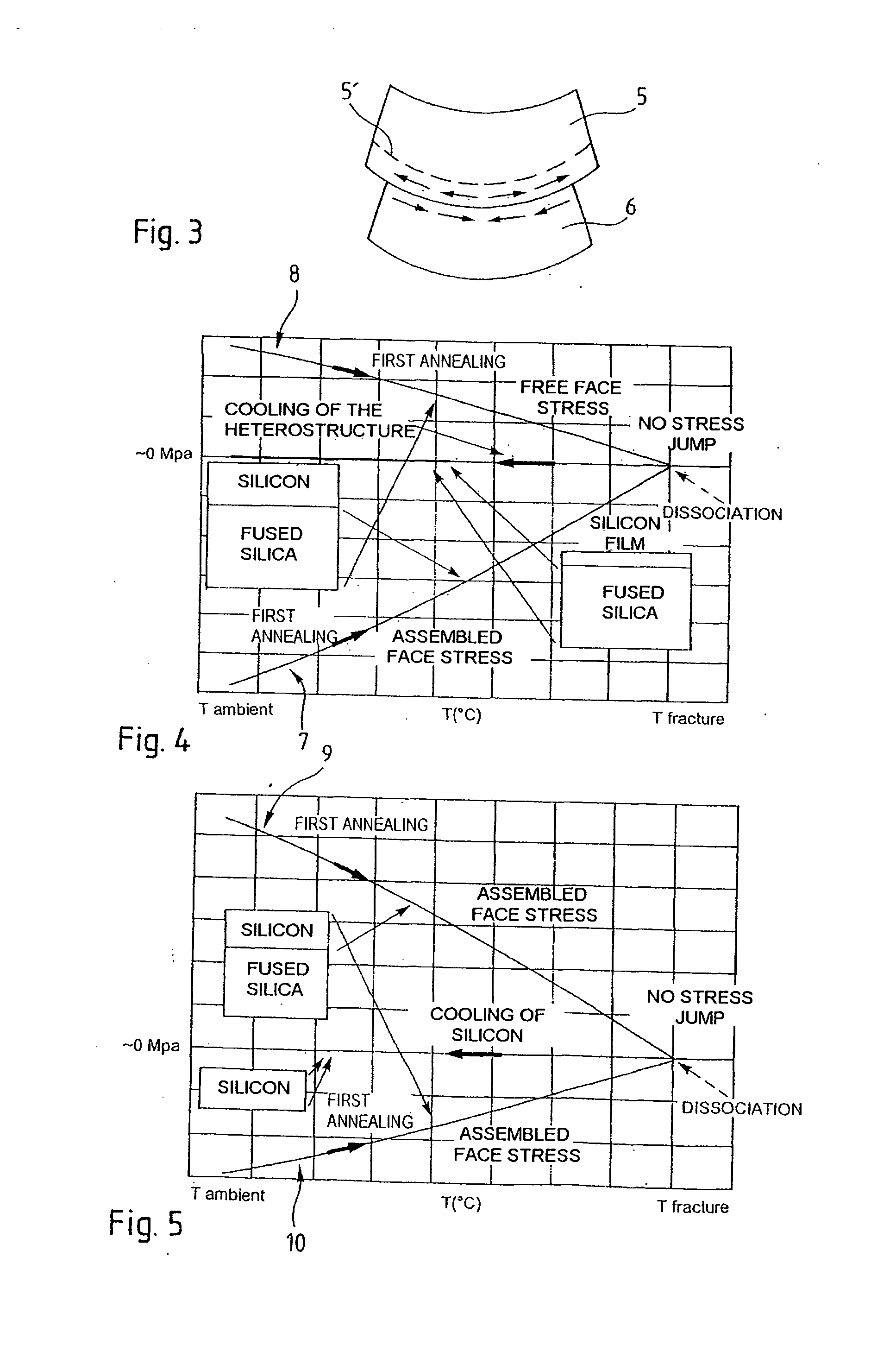
The invention proposes a method of producing a complex structure by assembling two substrates at their connecting faces, with a tangential stress state difference between the two faces to be dissociated at the moment of separation. This method allows for the intentional generation of stresses in the structure to compensate for stresses that will be generated when the temperature is increased to dissociate the structure. The invention also provides a technique for generating internal stresses in a complex structure, which can be difficult to adjust. The method is accurate and reproducible, and allows for the stresses to be monitored and controlled as a function of future requirements. The bonding forces between the substrates to be assembled are no longer limited, and the complex structure does not have to be separated during assembly.

Problems solved by technology

A problem can arise if heat treatment is required to induce some or all of the fracture in the weakened region and the source and target substrates feature materials with very different coefficients of thermal expansion.
Heat treatment can induce high internal stresses within the structure formed by assembling the two substrates, by virtue of the difference in their coefficients of thermal expansion, and these high internal stresses may damage the structure.
These stresses can also cause damage at the moment of fracture proper, since at this time the structures immediately relax when they are suddenly dissociated.
If its magnitude is too high, this jump can damage at least one of these two structures.
More generally, the problem is that of controlling the stresses within a heterostructure (i.e. a complex structure made by assembling at least two different materials) at the moment of dissociation of the heterostructure when that dissociation necessitates a change of temperature.

Method used


Image

  • Method for making a stressed structure designed to be dissociated
  • Method for making a stressed structure designed to be dissociated
  • Method for making a stressed structure designed to be dissociated

Examples


Embodiment Construction

[0057] In the figures to which the following description refers, identical, similar or equivalent parts are identified by the same reference numbers. Also, to clarify the figures, the various items are not represented to a consistent scale.

[0058] To illustrate the invention, there will be described by way of non-limiting example a method of transferring a film consisting of a layer of silicon approximately 0.4 μm thick and a layer of oxide approximately 0.4 μm thick from a 200 mm diameter surface-oxidized silicon source substrate 750 μm thick to a 200 mm diameter fused silicon target substrate 1200 μm thick.

[0059] The film may be transferred using the following method, employing standard transfer techniques:

[0060] ionically implanting the source substrate to create within that substrate a weakened region that delimits the thin layer to be transferred under implantation conditions known to the person skilled in the art, for example hydrogen implantation at a dosage of approximatel...


PUM


Abstract

The invention concerns a method of making a complex microelectronic structure by assembling two substrates through two respective linking surfaces, the structure being designed to be dissociated at a separation zone. The invention is characterized in that is consists, prior to assembly, in producing a state difference in the tangential stresses between the two surfaces to be assembled, said difference being selected so as to obtain in the assembled structure a predetermined stress state at the time of dissociation.

Description

TECHNICAL FIELD AND PRIOR ART [0001] The invention relates to a method of producing a complex microelectronic structure by assembling two basic microelectronic structures, this complex structure being intended to be dissociated. The microelectronic structure concept must be understood hereinafter as including optoelectronic, microtechnological, nanotechnological and nanoelectronic structures. [0002] The technique of transferring a layer from an original substrate to a temporary or final target substrate is increasingly used in microelectronics. This technique has many applications, of which only two will be mentioned here by way of illustrative and non-limiting example. For example, it is used to produce SOI (silicon on insulator) substrates used in particular to produce fast components with low power consumption. It is also used to produce composite substrates that limit costs by avoiding the use of costly bulk substrates. This is the case with bulk silicon carbide substrates, for ...

Claims


Application Information

Patent Timeline
Patent Type & Authority Applications(United States)
IPC IPC(8): H01L21/30H01L21/00H01L21/46H01L21/304H01L21/762
CPCH01L21/304H01L21/67092H01L21/76254
Inventor FOURNEL, FRANCKMORICEAU, HUBERTLAGAHE, CHRISTELLE
Owner COMMISSARIAT A LENERGIE ATOMIQUE ET AUX ENERGIES ALTERNATIVES
Learn More