Multi-band RF receiver
- Summary
- Abstract
- Description
- Claims
- Application Information
AI Technical Summary
Benefits of technology
Problems solved by technology
Method used
Image
Examples
Embodiment Construction
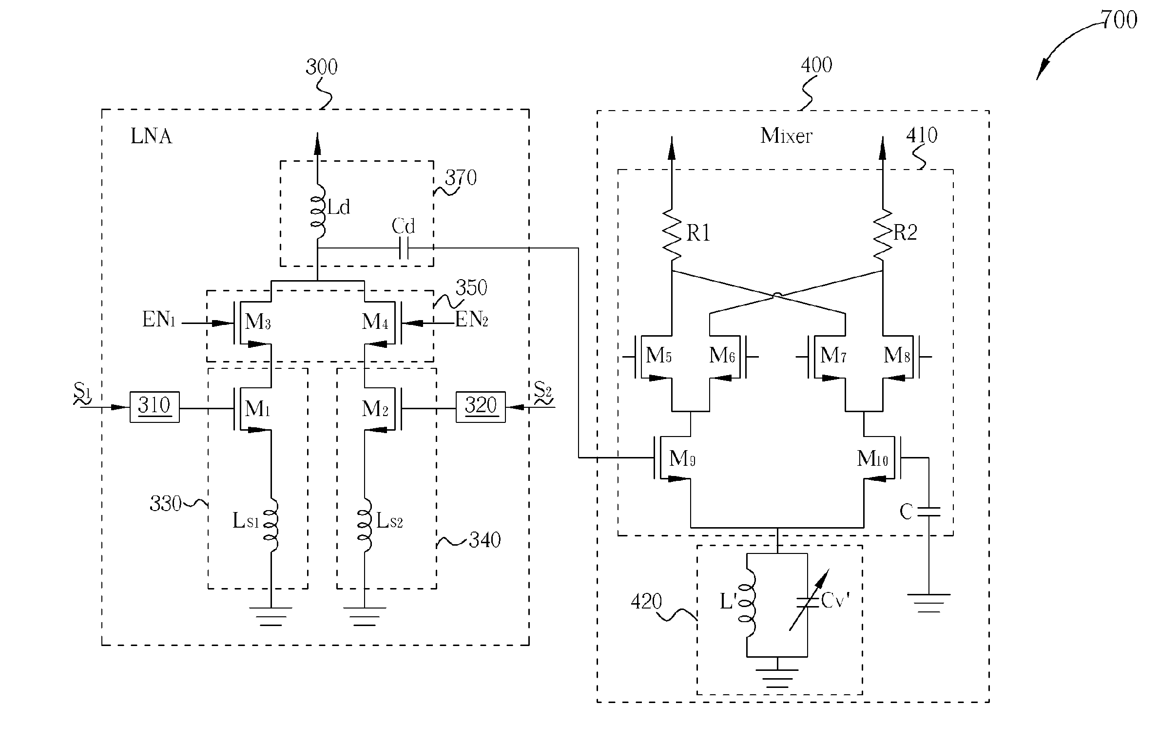
[0017] Please refer to FIG. 3, which is a diagram of a multi-band receiver 700 according to the present invention. The multi-band receiver 700 comprises an LNA 300 and a mixer 400. As shown in FIG. 3, the LNA 300 comprises a 2.4 G matching network 310, a 5 G matching network 320, a gain cell 330 coupled to the 2.4 G matching network 310, a gain cell 340 coupled to the 5 G matching network 320, a switching circuit 350 coupled to the gain cells 330, 340, and a loading circuit 370 coupled to the switching circuit 350. Here, the matching circuits 310, 320 are respectively utilized to receive input signals S1, S2 with specific frequencies (2.4 GHz and 5 GHz), where the functions and structures of the matching circuits 310, 320 are well known, and thus omitted here. The gain cells 330, 340 cooperate with the loading circuit 370 to amplify the received input signal S1, S2. Please note that in this embodiment, the loading circuit 370 is utilized to fixedly provide a specific load to the gai...
PUM
 Abstract
Description
Claims
Application Information
 - R&D
- Intellectual Property
- Life Sciences
- Materials
- Tech Scout
- Unparalleled Data Quality
- Higher Quality Content
- 60% Fewer Hallucinations
Browse by: Latest US Patents, China's latest patents, Technical Efficacy Thesaurus, Application Domain, Technology Topic, Popular Technical Reports.
© 2025 PatSnap. All rights reserved.Legal|Privacy policy|Modern Slavery Act Transparency Statement|Sitemap|About US| Contact US: help@patsnap.com


