
Low noise back EMF sensing brushless DC motor

a brushless dc motor and low noise technology, applied in the direction of field or armature current control, electronic commutator, synchronous motor starter, etc., can solve the problems of increasing cost, excessive space on the associated printed circuit board, and relatively high number of components of the bemf digitiser

Inactive Publication Date: 2006-09-07
FISHER & PAYKEL APPLIANCES LTD
View PDF8 Cites 31 Cited by
  • Summary
  • Abstract
  • Description
  • Claims
  • Application Information

AI Technical Summary

Benefits of technology

[0025] digitising means coupled to one or more of said windings for digitising the back EMF induced in said one or more windings by detecting the zero crossings of said back EMF signal; and
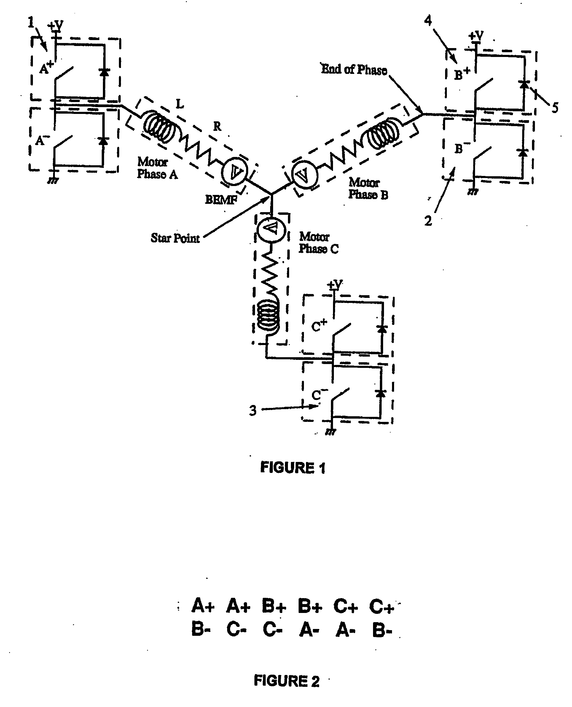
[0026] a microcomputer operating under stored program control, said microcomputer receiving said digitized back EMF signal and outputting switching signals for said switching devices, said microcomputer storing sequences of switching device state patterns for execution to produce switching signals to cause current to be commutated through successive combinations of all three of said windings such that magnetic flux produced by said stator windings rotates in a desired direction by 60° per commutation at a speed inversely proportional to the period between commutations; and

Problems solved by technology

But prior art ECMs using BEMF sensing have the problem in that the BEMF digitisers use a relatively high number of components, particularly high voltage resistors, which require excessive space on the associated printed circuit boards and increase cost.
Other problems are inherent in ECMs using BEMF sensing for rotor position and where it is not feasible to employ a PWM regime that will produce a pure sinusoidal winding current.
This noise problem is even more exacerbated when for reasons of economy only the lower (or only the upper) commutation switching devices in the commutation bridge are pulse width modulated.

Method used


Image

  • Low noise back EMF sensing brushless DC motor
  • Low noise back EMF sensing brushless DC motor
  • Low noise back EMF sensing brushless DC motor

Examples


Embodiment Construction

[0067] Preferred implementations of the invention will now be described.

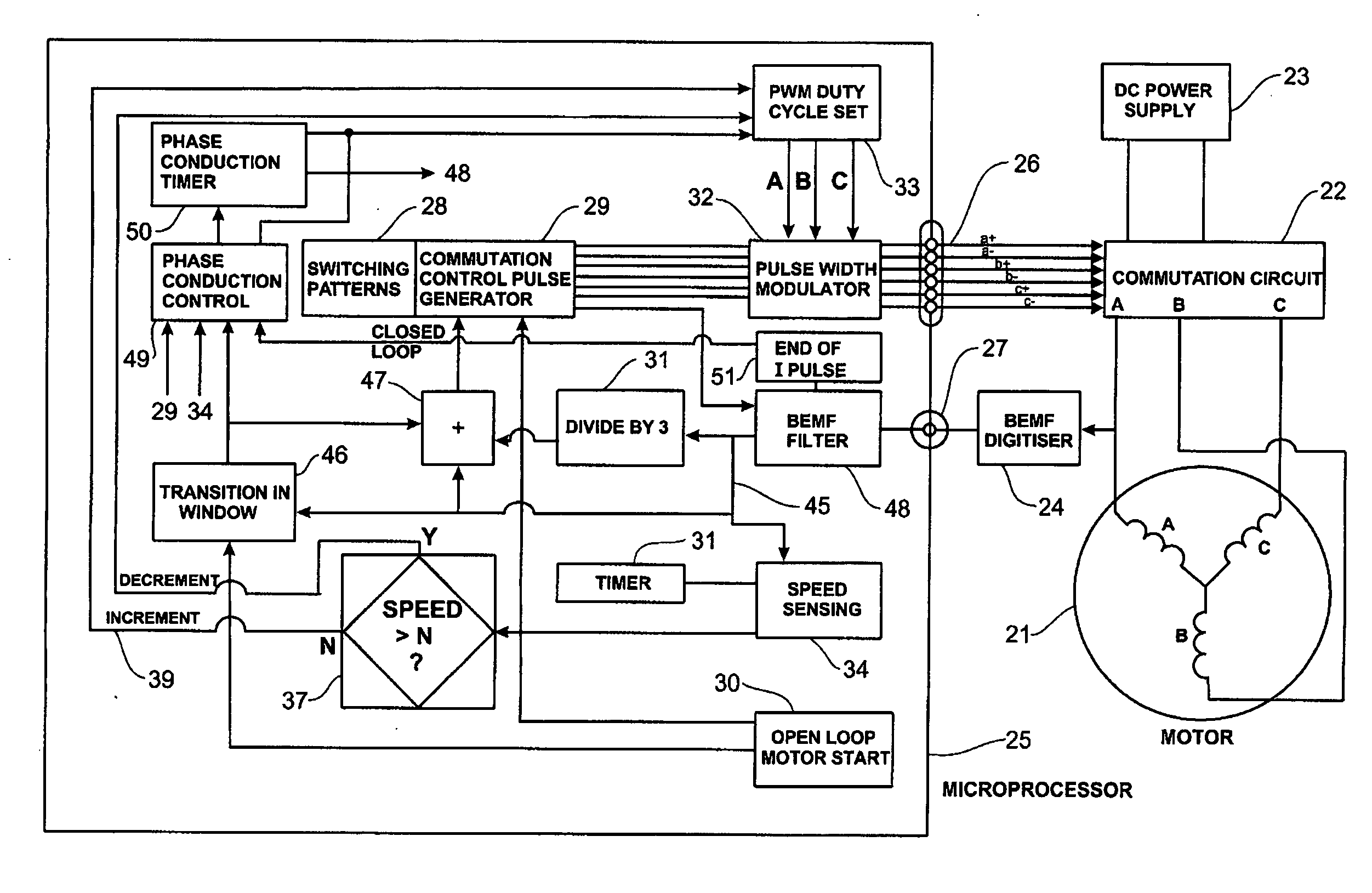
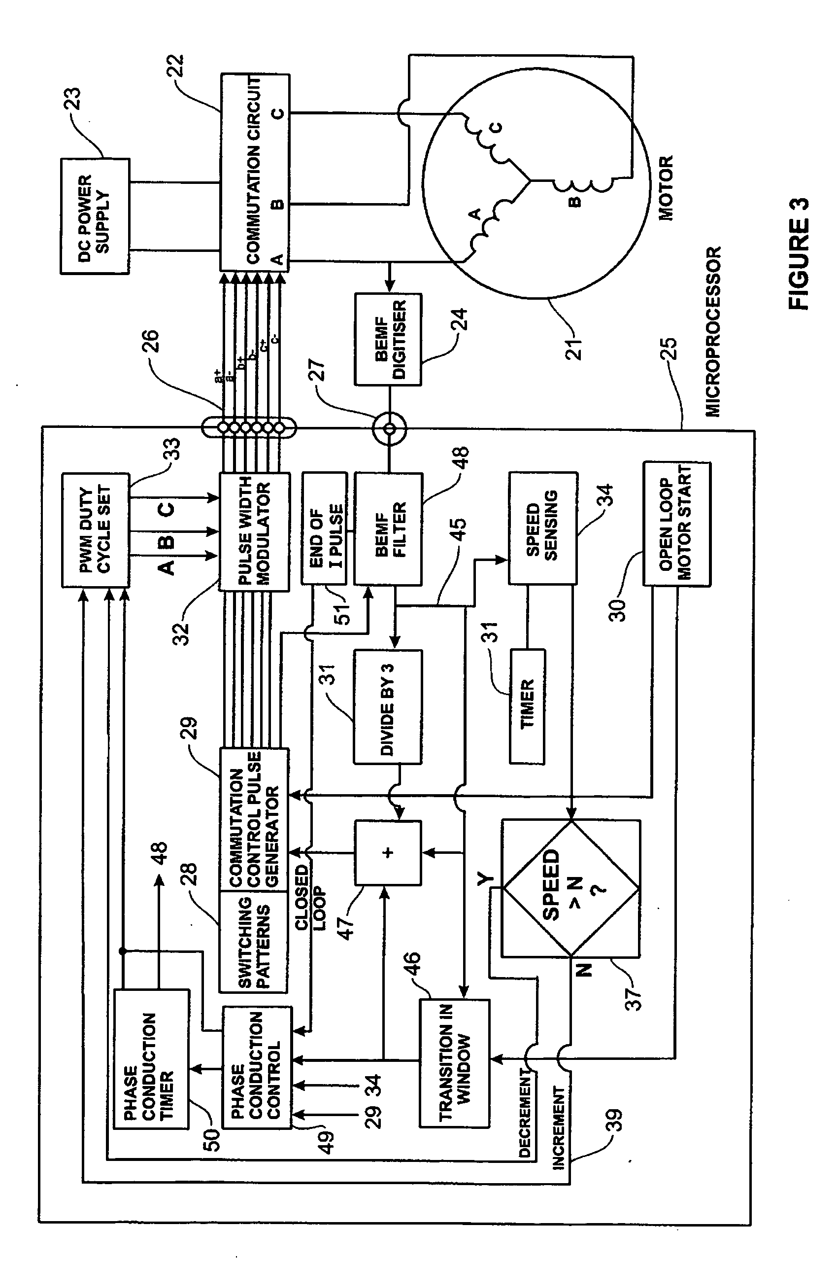
[0068]FIG. 3 shows one preferred form of the electronically commutated motor of the present invention in block diagram form. The main hardware blocks are a permanent magnet three winding motor 21, motor winding commutation circuit 22, DC power supply 23, back EMF digitiser 24 and a programmed microcomputer 25. In one preferred application where the motor 21 drives an impeller 61 in a pump 62 in a washing appliance (see FIG. 6) the microcomputer 25 will usually be the appliance microprocessor which will be responsible for all other appliance control functions; including control of a main motor for spin and wash actions in the case of a clothes washing machine.

[0069] The present electronically commutated motor (ECM) system is described in relation to a preferred form of motor having a stator with three windings (or phases) A, B and C and six salient poles. Other stator configurations could be used. The motor has...


PUM


Abstract

A low noise electronic three phase bridge controlled brushless DC motor suitable for whiteware appliance pumps and other appliance applications. Back EMF zero crossing sensing is used to determine rotor position and thus stator winding commutation times. Motor torque and speed are controlled by pulse width modulating the operation of that bridge switching device which has just been switched from an OFF state to an ON state on each new commutation. All three stator windings have current flowing in each winding commutation to improve motor current waveform and thereby reduce motor noise, but the current in one winding is always terminated before the end of the commutation period to allow the back EMF in that winding to be sensed to zero crossing.

Description

[0001] This application claims the benefit of U.S. provisional application Ser. No. 60 / 659,375, filed on Mar. 7, 2005 and entitled Low Noise Back EMF Sensing Brushless DC Motor.TECHNICAL FIELD [0002] This invention relates to electronically controlled brushless DC (BLDC) motors (having permanent magnet rotors) and in particular, but not solely, to three winding motors for fractional horsepower applications such as in home appliances and healthcare equipment. In a laundry machine such electronically controlled motors may be used to power the wash and spin motion of an agitator or drum and / or the wash bowl drain and recirculating pumps. PRIOR ART [0003] Methods of controlling electronically commutated brushless DC motors have been disclosed in U.S. Pat. No. 4,495,450 (Tokizaki et al, assigned to Sanyo Electric Co Ltd) and for use in home appliances and in particular laundry washing machines in U.S. Pat. No. 4,540,921 (Boyd et al, assigned to General Electric Company), U.S. Pat. No. 4,...

Claims


Application Information

Patent Timeline
Patent Type & Authority Applications(United States)
IPC IPC(8): H02P25/12
CPCH02P6/182H02P7/06
Inventor HARWOOD, JONATHAN DAVID
Owner FISHER & PAYKEL APPLIANCES LTD
Learn More