
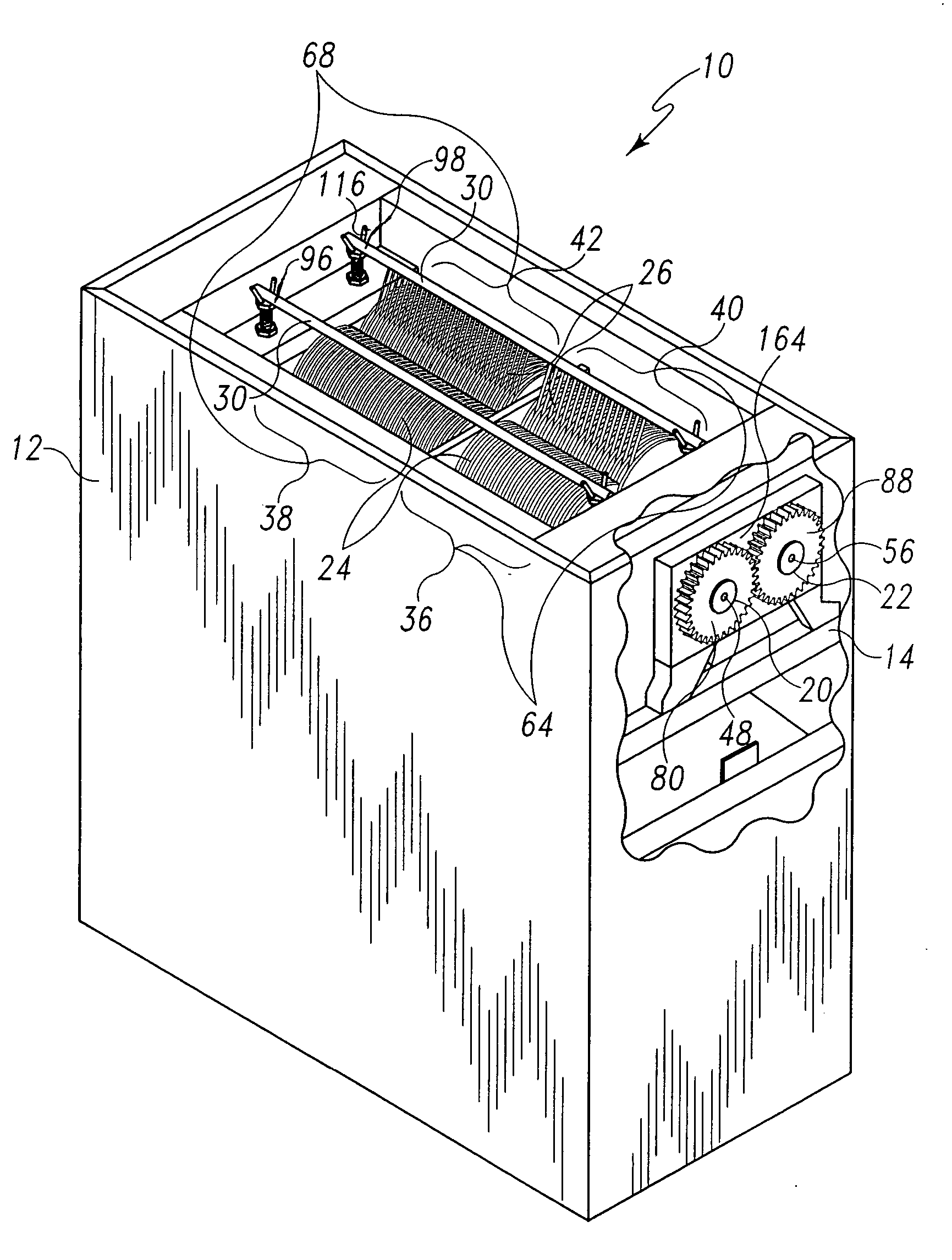
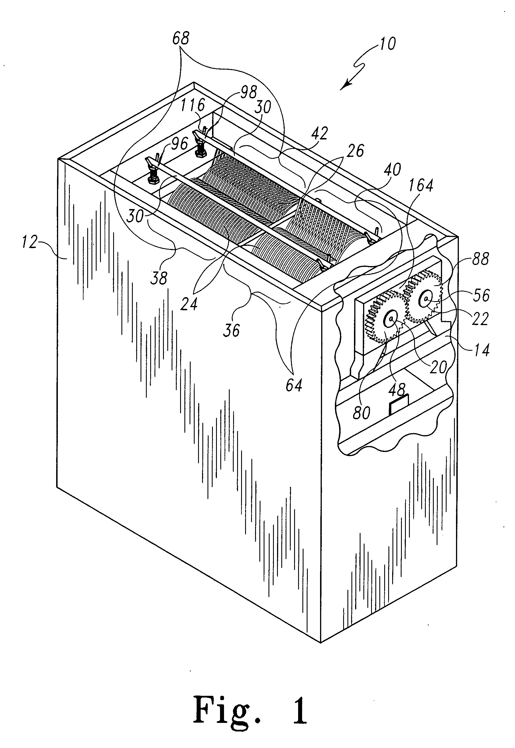
Food processing apparatus for forming strips, slices and cubes

a technology of food processing apparatus and cutting machine, which is applied in the field of food processing machines, can solve the problems of unsightly strips or cubes, easy to tear or drag the cutting of cooked meat, and laborious and slow process of cutting meat into slices, strips or cubes by hand

Active Publication Date: 2006-09-07
CHEN ZHUI
View PDF35 Cites 8 Cited by
  • Summary
  • Abstract
  • Description
  • Claims
  • Application Information

AI Technical Summary

Benefits of technology

[0007] In restaurants which serve Chinese cuisine, it is much more efficient and economical to cook the meat before slicing or cubing it. Cooked meat loses most of the glutinous tendencies of raw meat and thus is less likely to cling to the cutting blades or to wrap around the shafts. On the other hand, cooked meat is more susceptible to tearing or ragged cutting. Thus, in an apparatus of the type shown in the Deckert patent, the toothed tenderizing wheels, if used with cooked meat, would tend to tear the meat, resulting in unsightly strips or cubes. Even arrangements such as in the Huse apparatus, which apparently does not use toothed tenderizing wheels to tenderize the meat, tend to make ragged shallow cuts in the meat.

Problems solved by technology

Cutting meat into slices, strips or cubes by hand can be a laborious and slow process, and uniformity of the slices, strips or cubes depends upon the skill of the person doing the cutting.
On the other hand, cooked meat is more susceptible to tearing or ragged cutting.
Thus, in an apparatus of the type shown in the Deckert patent, the toothed tenderizing wheels, if used with cooked meat, would tend to tear the meat, resulting in unsightly strips or cubes.
Even arrangements such as in the Huse apparatus, which apparently does not use toothed tenderizing wheels to tenderize the meat, tend to make ragged shallow cuts in the meat.

Method used


Image

  • Food processing apparatus for forming strips, slices and cubes
  • Food processing apparatus for forming strips, slices and cubes
  • Food processing apparatus for forming strips, slices and cubes

Examples


first embodiment

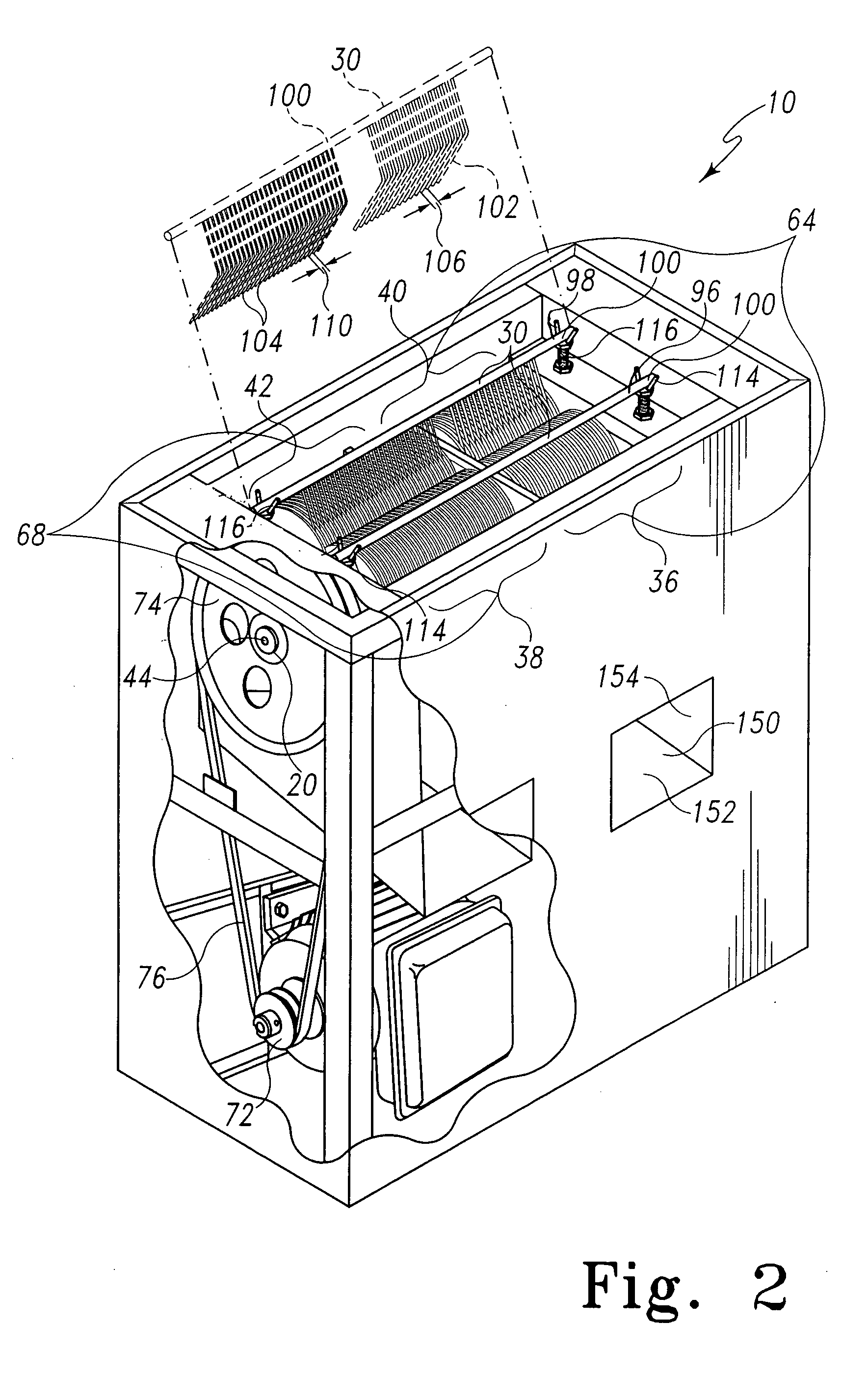
[0041] In food processor 10, the first set of blades 24 is driven by the motor 16 coupled to the shaft 20 to which the blades 24 are mounted by the linkage 18. In the illustrated embodiment, the linkage 18 comprises a drive pulley 72, a driven pulley 74, and a belt 76. In the first illustrated embodiment, each of the pulleys 72, 74 is configured to include a single channel for receipt of the belt 76 therein. Those skilled in the art will recognize that pulleys configured to drive and be driven by dual belts could be utilized within the scope of the disclosure, as shown, for example, in FIGS. 9 and 10.

[0042] The driven pulley 74 has a diameter greater than the diameter of the drive pulley 72 to which it is coupled by the belt 76. The drive pulley 72 is coupled to the drive shaft of the motor 16. The driven pulley 74 is coupled to one end 44 of the shaft 20. Due to the relative size of the driven pulley 74 and the drive pulley 72, the angular velocity of the shaft 20 is smaller than t...

second embodiment

[0044] In food processor, the first set of blades 24 is driven by the motor 16 coupled to the shaft 20 to which the blades 24 are mounted by the linkage 618. In the illustrated embodiment, the linkage 618 comprises a dual drive pulley 672, a dual driven pulley 674, two belts 676, 678, a reduction shaft 671, a large reduction pulley 673, a small reduction pulley 675 and two belts 677, 679. In the illustrated embodiment, each of the pulleys 672, 674, 673, 675 is configured to include two channels for receipt of two belts therein. Those skilled in the art will recognize that pulleys configured to drive and be driven by a single belt could be utilized within the scope of the disclosure.

[0045] The large reduction pulley 673 is coupled to one end of the reduction shaft 671 and the small reduction pulley 675 is coupled to the opposite end of the reduction shaft 671. The large reduction pulley 673 has a diameter greater than the diameter of the drive pulley 672 to which it is coupled by the...


PUM

PropertyMeasurementUnit
Diameteraaaaaaaaaa
Speedaaaaaaaaaa
Dimensionaaaaaaaaaa

Abstract

A food processing apparatus for slicing food into slices, strips and cubes comprises a frame, a first and second shaft and first, second, third and fourth subsets of blades. The first shaft is coupled to the frame for rotation relative to the frame about a longitudinal axis of the first shaft. The second shaft is coupled to the frame for rotation relative to the frame about a longitudinal axis of the second shaft. The longitudinal axis of the second shaft is disposed substantially parallel to the longitudinal axis of the first shaft and is displaced therefrom. The first and second subsets of blades are mounted to the first shaft. Each blade of the first subset of blades is displaced along the longitudinal axis of the first shaft from adjacent blades of the first subset of blades by a first displacement. Each blade of the second subset of blades is displaced along the longitudinal axis of the first shaft from adjacent blades of the second subset of blades by a second displacement differing from the first displacement. The third and fourth subsets of blades are mounted to the second shaft. Each blade of the third subset of blades is displaced along the longitudinal axis of the second shaft from adjacent blades of the third subset of blades by the first displacement. Each blade of the fourth subset of blades is displaced along the longitudinal axis of the second shaft from adjacent blades of the fourth subset of blades by the second displacement. The first subset of blades cooperate with the third subset of blades to form a first cutting region therebetween for cutting food to a first dimension and the second subset of blades cooperate with the fourth subset of blades to form a second cutting region therebetween for cutting food to a second dimension.

Description

BACKGROUND AND SUMMARY [0001] This invention relates to food processing machines, and, more particularly, to a meat slicing machine capable of forming slices, strips and cubes from frozen, cooked or raw meat. [0002] In the restaurant industry and particularly in the Chinese food restaurant industry, it is common for food, and in particular meat, to be cut into slices, strips and cubes. Cutting meat into slices, strips or cubes by hand can be a laborious and slow process, and uniformity of the slices, strips or cubes depends upon the skill of the person doing the cutting. In Chinese cooking “slices” are slabs of meat typically approximately four millimeters thick having varying lengths and widths. “Strips” are long pieces of meat about typically four millimeters thick and eight millimeters wide. “Cubes” are typically eight millimeters wide, eight millimeters thick and eight millimeters long. [0003] There are, in the prior art, numerous examples of apparatus for slicing meat into stri...

Claims


Application Information

Patent Timeline
IPC IPC(8): B23D19/00B23D19/04
CPCB26D3/22B26D7/06B26D7/0641Y10S83/932Y10T83/6587Y10T83/6588Y10T83/727Y10T83/739Y10T83/7751Y10T83/783Y10T83/7843
Inventor CHEN, ZHUI
Owner CHEN ZHUI
Learn More