
Percutaneous diagnostic and therapeutic hematoma drain

a technology of hematoma and percutaneous drainage, applied in the field of medical devices, can solve the problems of affecting the treatment effect of patients, affecting the treatment effect, and increasing the potential for hematoma, so as to prevent complications from occurring

Inactive Publication Date: 2006-08-31
OPIE JOHN C +1
View PDF8 Cites 20 Cited by
  • Summary
  • Abstract
  • Description
  • Claims
  • Application Information

AI Technical Summary

Benefits of technology

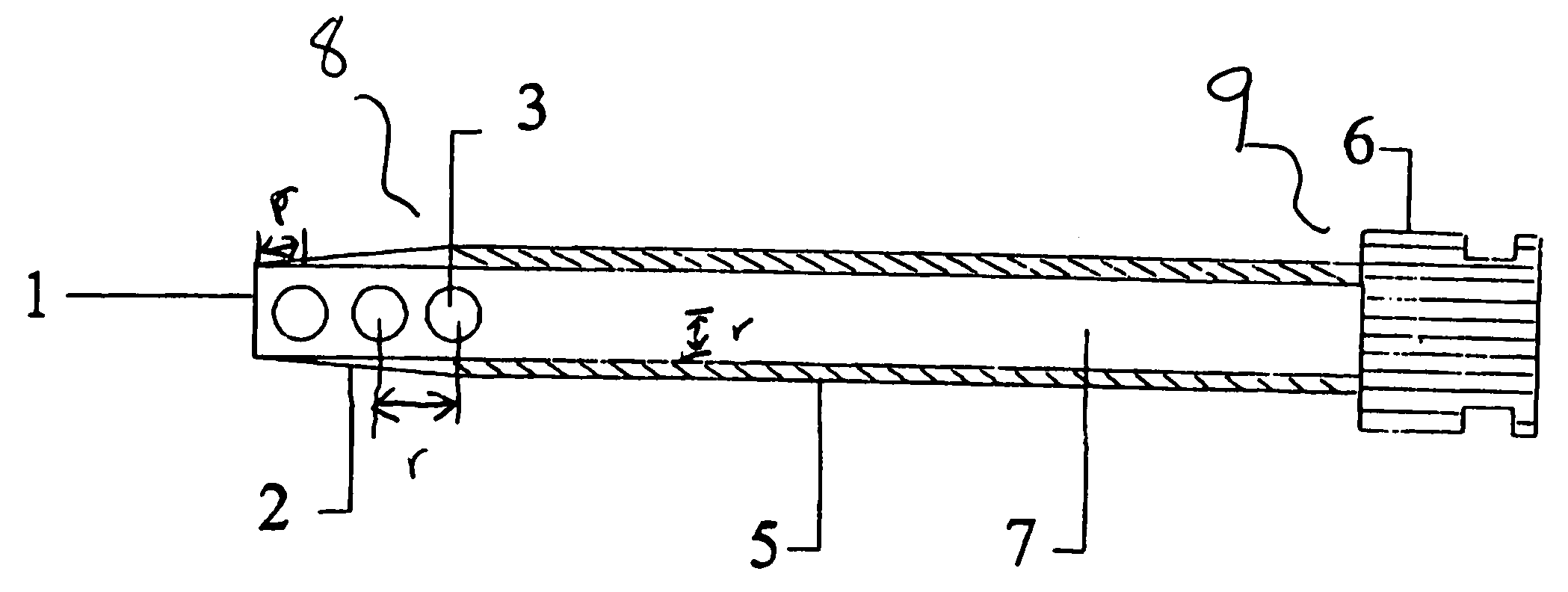
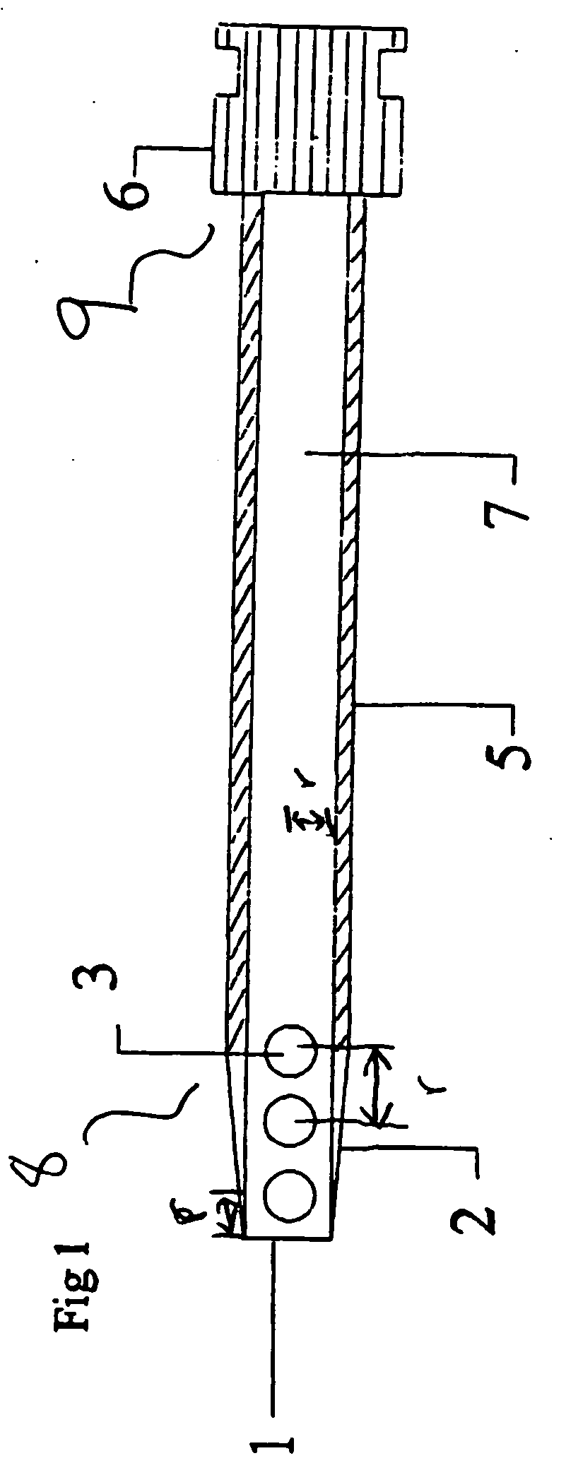
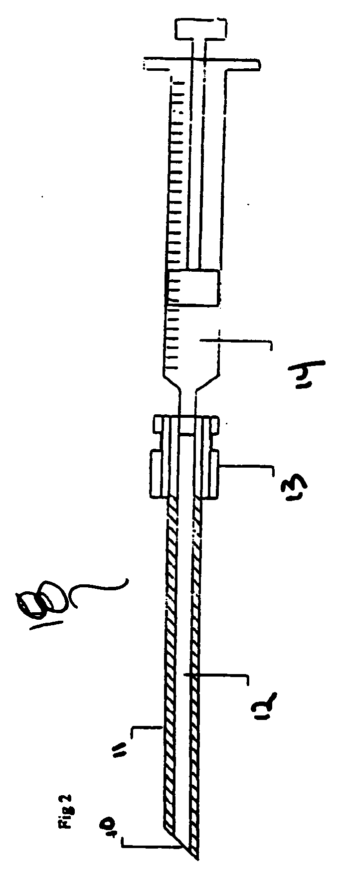
[0013] When in place, the connector of the drain is connected to an outflow tube which is connected to a vacuum reservoir. A vacuum is created in the system and any blood or body fluids that may be leaking in the patient are sucked into the drain, through the outflow tube, and into the reservoir. As any blood moving into the reservoir is visible, the drain effectively unmasks a concealed hemorrhage following a vascular access procedure. In addition to unmasking the hemorrhage, the drain provides a pathway for blood to be vented from the body, thus preventing a complications from occurring.

Problems solved by technology

These latter arterial punctures set up the potential for a hematoma (i.e., a localized swelling filled with blood resulting from a break in a blood vessel) due to sheath pull out pressure control problems.
The main problem with the latter devices is that they are applied in a blind percutaneous (i.e., through the skin) manner and thus can and do fail.
In certain situations, the site selected for pressure and or closure, entirely misses the femoral artery puncture site with adverse consequences for the patient.
Failure under these circumstances results in a concealed hematoma, which may develop into a substantial false aneurysm (i.e., a pulsating, encapsulated hematoma communicating with a ruptured vessel) and require definitive vascular surgical repair.
However, this may take some hours.
The patient typically experiences pain for days if not weeks and has difficulty bending the hip joint.
Not uncommonly, major problems develop and anterior thigh compartment compression syndrome occurs.
This leads to pronounced patient distress due to a large or very large concealed hemorrhage.
In extreme situations, such hematomas may result in leg amputation and rarely death.
The process is both exciting and dangerous for all concerned.
However, such “blind” techniques can and do fail.
As such, current technology does not provide desirable methods and devices for detection, prevention, and early correction of failures and hematomas resulting from vascular procedures.

Method used


Image

  • Percutaneous diagnostic and therapeutic hematoma drain
  • Percutaneous diagnostic and therapeutic hematoma drain
  • Percutaneous diagnostic and therapeutic hematoma drain

Examples


Embodiment Construction

[0021] Reference will now be made in detail to the present exemplary embodiments of the invention, examples of which are illustrated in the accompanying drawings.

[0022] The hematoma drain according to the invention is an “early warning” percutaneously-placed drainage device designed as a diagnostic measure to alert the staff that hemostasis (i.e., the stoppage of bleeding or hemorrhage) might not be secure, and if a bleed does occur, it will evacuate blood before a hematoma forms and will help prevent greater complications. In addition, use of the hematoma drain will permit secondary procedures to occur earlier and will limit some occasional compression syndromes which might occur after the drain has been removed. The drain will be expected to become active only after the sheath is removed, however the drain may be active while the sheath is still in place. Typically, the period of use of the hematoma drain may vary between 1 and 3 hours before the sheath is pulled.

[0023] At the c...


PUM


Abstract

The invention provides an over-the-needle, percutaneously-placed hematoma drain designed to aid in preventing, detecting, and draining a concealed hemorrhage while the drain is in place. It is designed to provide an early warning that vascular hemostasis following vascular access device removal may not be adequate for patient discharge.

Description

RELATED APPLICATIONS [0001] This application claims priority to U.S. Provisional Patent Application No. 60 / 612,909 filed on Sep. 24, 2004 which is hereby incorporated by reference herein. In addition, the following related utility and provisional applications are also incorporated by reference herein: [0002]“Surgical Drains” by John Opie et al.—U.S. Patent Publication No. 2005 / 0004536, published Jan. 6, 2005 from U.S. patent application Ser. No. 10 / 863,009 filed on Jun. 7, 2004 which claims priority from Provisional Application No. 60 / 476,663 filed on Jun. 5, 2003. “Fluid Evacuator System” by John Opie—PCT Publication No. WO-05 / 072789, published Aug. 11, 2005 from PCT Application No. US05 / 03128 filed on Jan. 26, 2005 which claims priority from U.S. Provisional Application No. 60 / 539,138 filed on Jan. 26, 2004.FIELD OF THE INVENTION [0003] The present invention relates to medical devices, and more particularly, to an over-the-needle, percutaneously-placed drain designed to aid in pre...

Claims


Application Information

Patent Timeline
IPC IPC(8): A61M27/00
CPCA61M25/0606A61M27/00
Inventor OPIE, JOHN C.IZDEBSKI, THOMAS
Owner OPIE JOHN C
Learn More