Ball Joint

a ball joint and ball joint technology, applied in the field of ball joints, can solve the problems of unsatisfactory sealing, and achieve the effects of improving the wear resistance of the second lip portion, improving sealing, and improving sealing

Inactive Publication Date: 2006-08-31
SOMIC ISHIKAWA INC
View PDF12 Cites 6 Cited by
  • Summary
  • Abstract
  • Description
  • Claims
  • Application Information

AI Technical Summary

Benefits of technology

[0006] A ball joint of the present invention comprises: a housing with an opening portion; a ball head portion rotatably housed in this housing; a ball stud with a stud portion provided in a protruding manner from this ball head portion, protruding from the opening portion and a brim portion provided in a protruding manner on an outside surface of this stud portion; and an elastic approximately pipe-formed dust cover inserted through the stud portion, provided across an outside surface of the housing and an outside surface of the stud portion so as to block the opening portion, wherein the dust cover is provided with a first lip portion which is closely fitted in a manner urged toward a ball head portion-side end face of the brim portion and a second lip portion which is closely fitted in a manner urged toward an outside surface of the brim portion. And, by providing an elastic cover, between the outside surface of the housing and outside surface of the stud portion provided in a protruding manner from the ball head portion, protruding from the opening portion of the housing, so as to block the opening portion of the housing, and by providing this dust cover with a first lip portion which is closely fitted in a manner urged toward a ball head portion-side end face of the brim portion provided in a protruding manner on the ball stud and a second lip portion which is closely fitted in a manner urged toward an outside surface of the brim portion, for example, in a case where the ball stud is relatively greatly swayed with respect to the housing, the first lip portion and second lip portion securely follow the brim portion of the ball stud and are closely fitted, therefore, sealing can be made satisfactory.
[0007] Moreover, in the ball joint of the present invention, the first lip portion is, in a manner urged toward a ball head portion-side end face of the brim portion, closely fitted like a surface to a part of this end face. And, by close-fitting of the first lip portion, in a manner urged toward a ball head portion-side end face of the brim portion, like a surface to a part of the end face, an urging force applied from the first lip portion to the ball head portion-side end face of the brim portion is more securely transmitted to the ball head portion-side end face of the brim portion, therefore, sealing can be improved.
[0008] Furthermore, in the ball joint of the present invention, the second lip portion is, in a manner urged toward an outside surface of the brim portion, closely fitted like a surface to a part of this outside surface. And, by close-fitting of the second lip portion, in a manner urged toward an outside surface of the brim portion, like a surface to a part of the outside surface, an urging force applied from the second lip portion to the outside surface of the brim portion is more securely transmitted to the outside surface of the brim portion, therefore, sealing can be improved.
[0009] Moreover, in the ball joint of the present invention, the dust cover is provided with a pocket portion provided between the first lip portion and second lip portion and brim portion of the ball stud, retaining a lubricant member inside. And, by providing a pocket portion between the first lip portion and second lip portion of the dust cover and brim portion of the ball stud, retaining a lubricant member inside, wear resistance of the second lip portion can be improved, and a co-rotation of the ball stud and dust cover can be prevented to secure sealing.

Problems solved by technology

However, in the above-described ball joint, when the ball stud is relatively greatly swayed with respect to the housing, since the lip portion of the dust cover is no longer closely fitted to the outer circumferential surface of the brim portion of the ball stud and a gap is created between the lip portion and outer circumferential surface of the brim portion, sealing is not satisfactory, wherein exists a problem.

Method used


Image

  • Ball Joint
  • Ball Joint
  • Ball Joint

Examples


Embodiment Construction

[0012] Hereinafter, an embodiment of the present invention will be described with reference to the drawings.

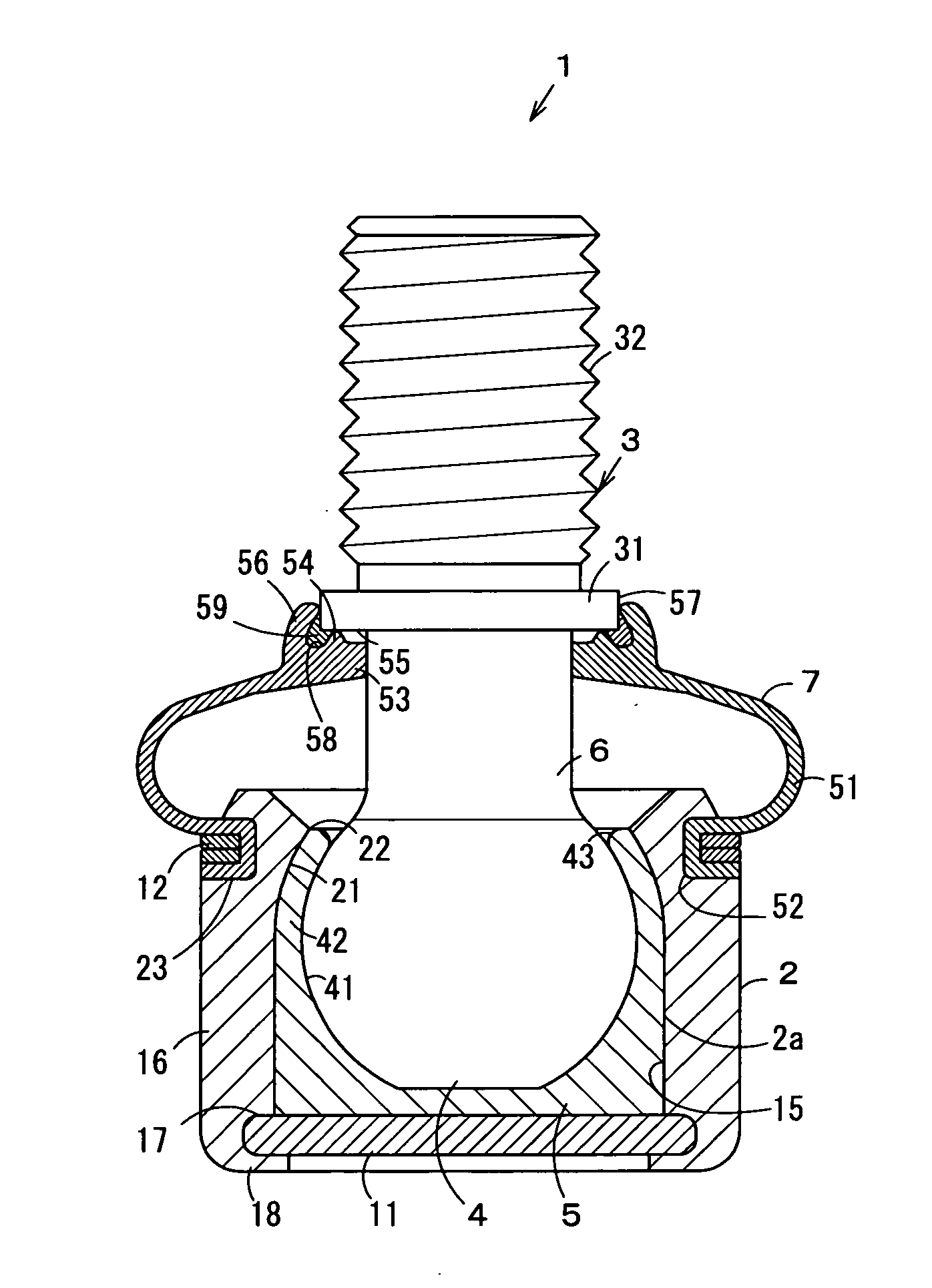
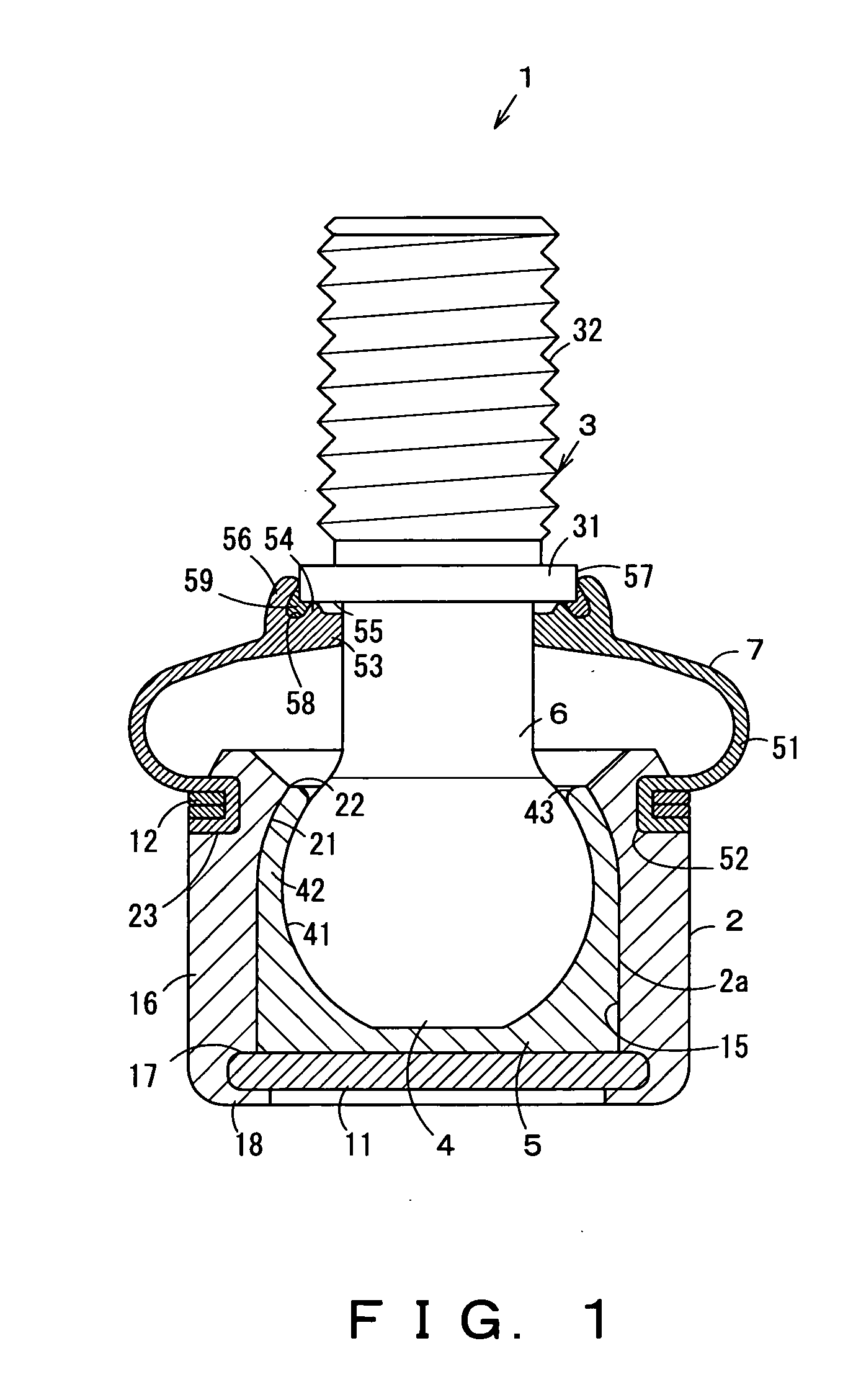
[0013] In FIG. 1, 1 denotes a ball joint. This ball joint 1 is used in, for example, a suspension device (suspension mechanism), steering device (steering mechanism) or the like of an automobile, etc.

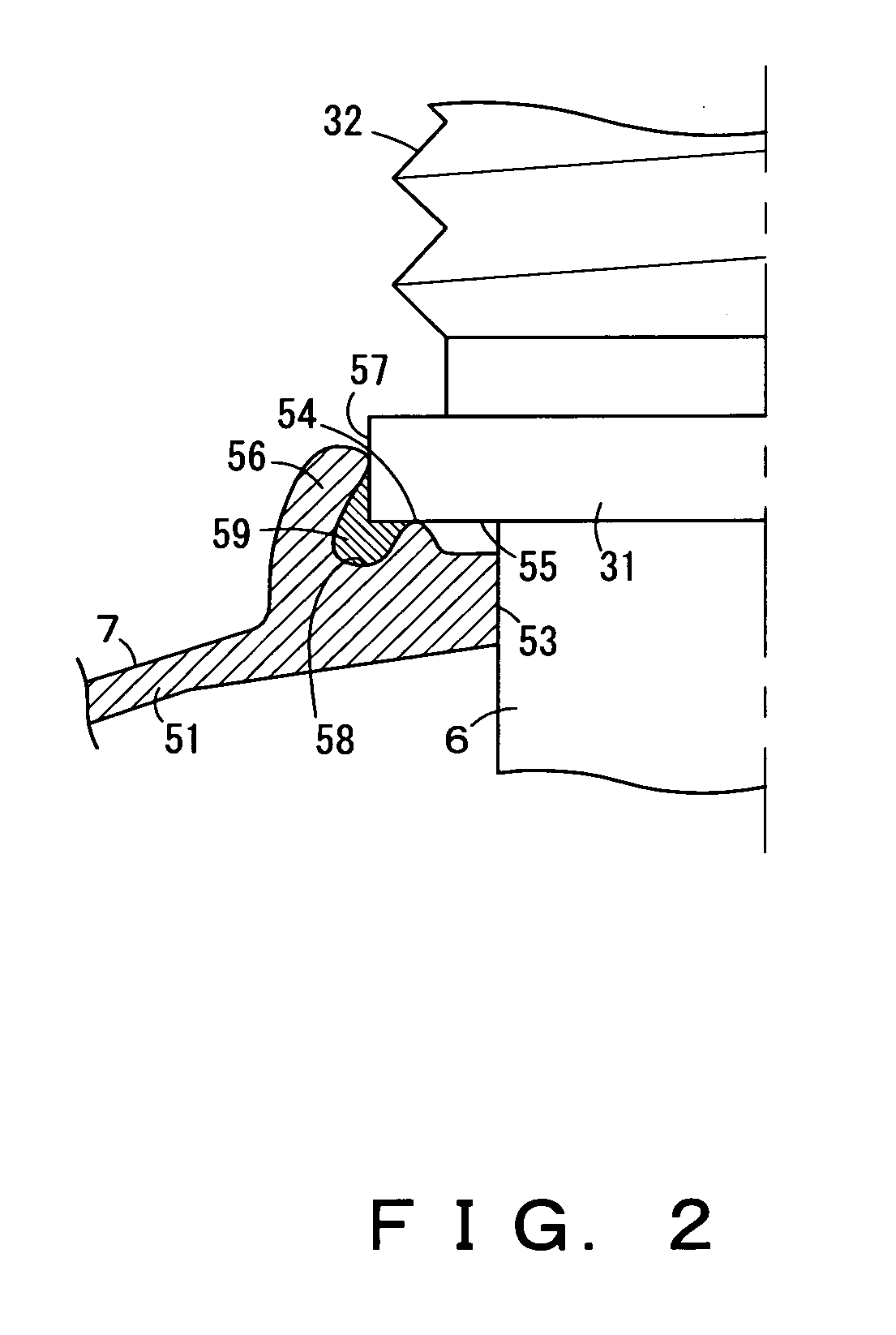
[0014] As this ball joint 1, in an inner chamber 2a of an approximately cylindrical housing 2 made of a metal or the like, a ball portion 4 as a ball head portion of a ball stud 3 made of steel or the like is rotatably fitted via a ball seat 5 as a bearing sheet integrally formed of a synthetic resin or a synthetic resin and a cushion material. And, between an outer circumferential surface that is an outside surface of the housing 2 and an outer circumferential surface that is an outside surface of a stud portion 6 as a shaft portion of the ball stud 3, a dust cover 7 is attached. This dust cover 7 is formed of an elastically deformable rubber or a soft synthetic resin, etc., in...


PUM


Abstract

An elastic dust cover, disposed between the outer circumferential surface of a housing and outer circumferential surface of a stud portion of a ball stud, is attached in a manner blocking an opening portion of the housing. In the dust cover, a first lip portion which is closely fitted in a condition urged toward an end face on a ball portion-side of a brim portion of a ball stud is provided. Even in a case where the ball stud is relatively greatly swayed with respect to the housing, since the first lip portion and a second lip portion follow the brim portion to be closely fitted, sealing can be satisfactorily provided.

Description

TECHNICAL FIELD [0001] The present invention relates to a ball joint having a housing provided with a dust cover. BACKGROUND ART [0002] For example, ball joints used in suspension devices (suspension mechanisms) or steering gears (steering mechanisms) of automobiles are known. [0003] As a ball joint of this type, a ball joint as described in, for example, Japanese Laid-open Utility Model Publication No. 1-139119 (Page 5-Page 8, FIG. 1-FIG. 3) is known. This ball joint comprises a ball stud having a ball portion as a ball head portion and a stud portion as a to-be-fixed portion provided in a protruding manner from this ball portion. The ball portion of this ball stud is rotatably housed in an approximately cylindrical housing. In addition, the stud portion of the ball stud is protruded outside through an opening portion on one axial end side of the housing. Furthermore, on the outer circumferential surface of this stud portion, an approximately ring-formed brim portion is integrally ...

Claims


Application Information

Patent Timeline
Patent Type & Authority Applications(United States)
IPC IPC(8): F16C11/00F16C11/06
CPCF16C11/0671F16C11/0633Y10T403/32631F16C2326/24B60G2204/416F16C2326/05B60G2204/148B60G7/005
Inventor SUZUKI, KEIICHIRO
Owner SOMIC ISHIKAWA INC
Why Eureka
Try Eureka