
Hardware abstraction layer

Active Publication Date: 2006-08-31
IP INFUSION INC
View PDF7 Cites 293 Cited by
  • Summary
  • Abstract
  • Description
  • Claims
  • Application Information

AI Technical Summary

Benefits of technology

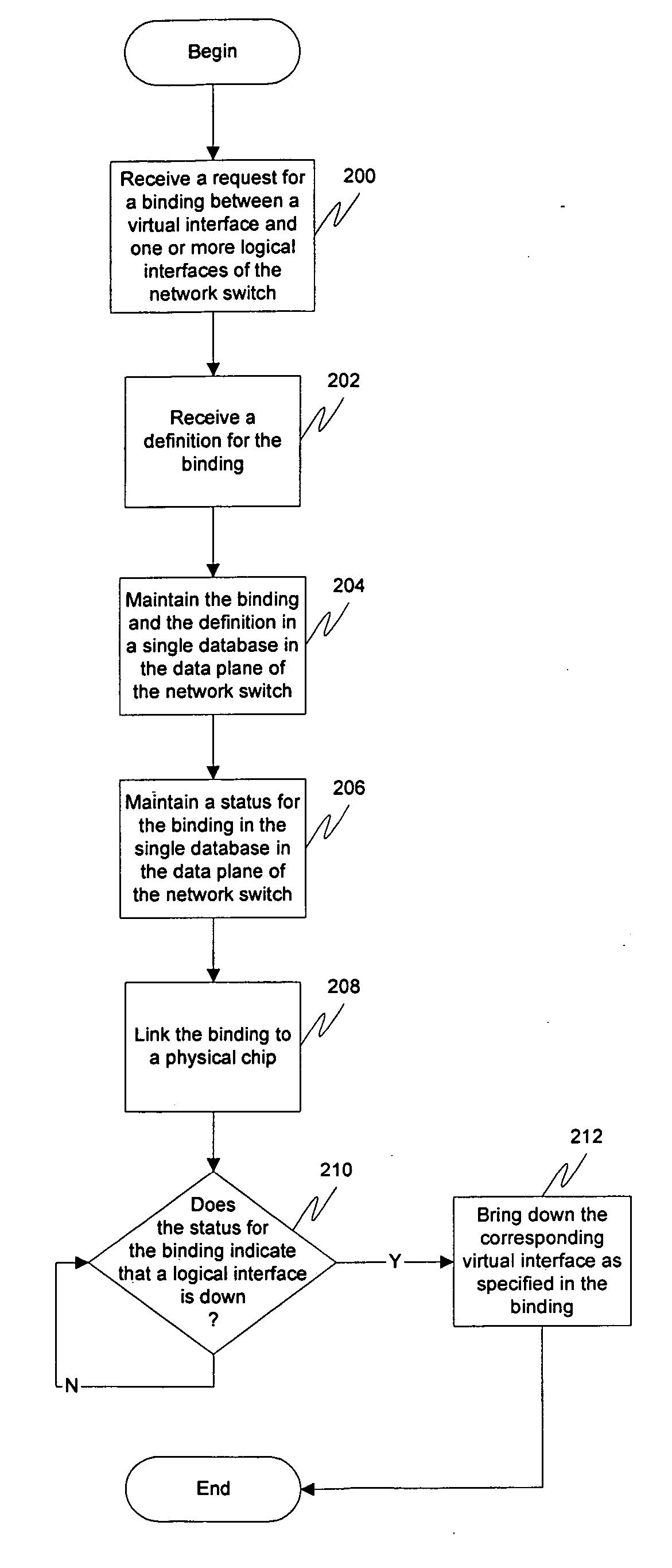
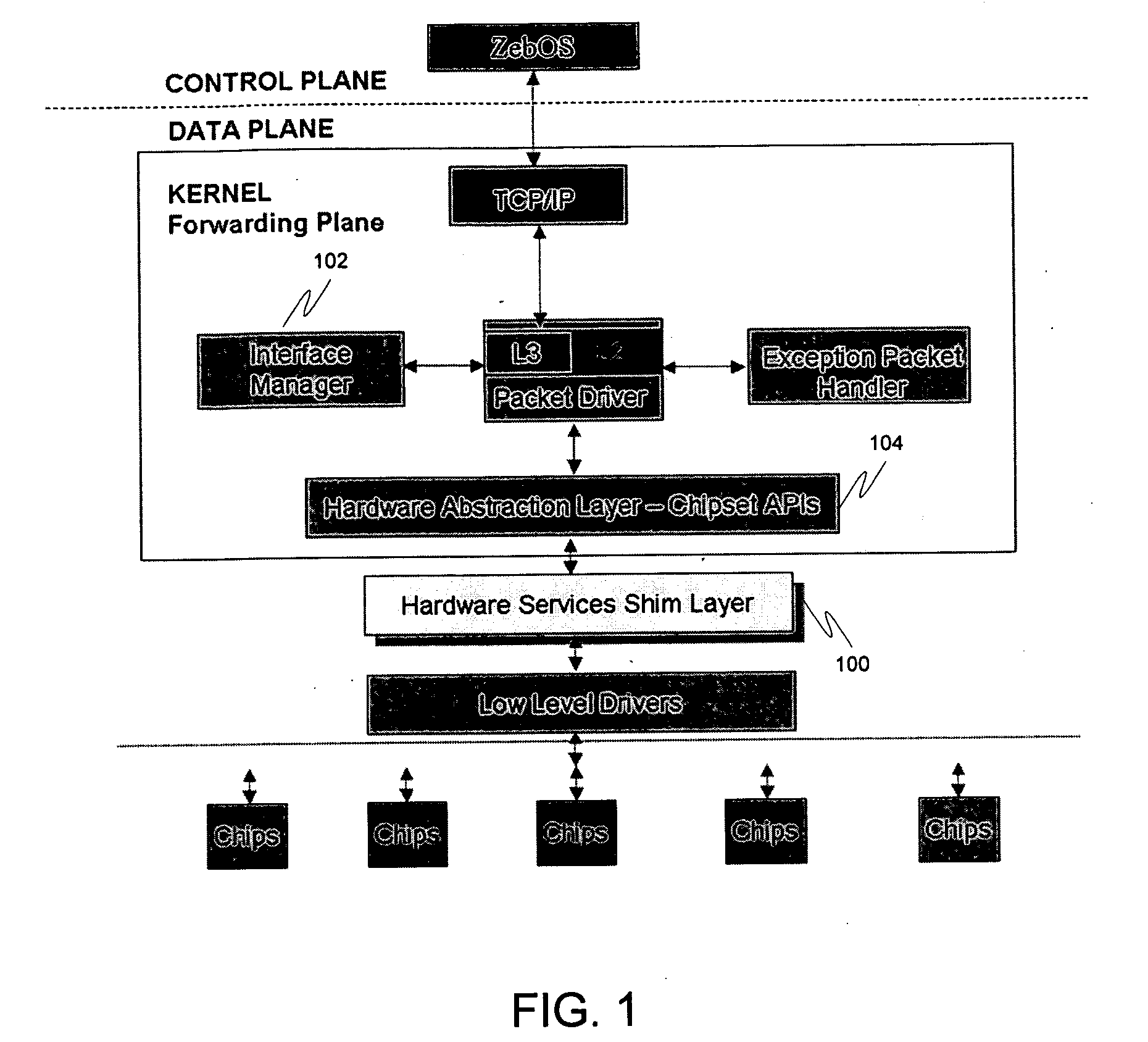
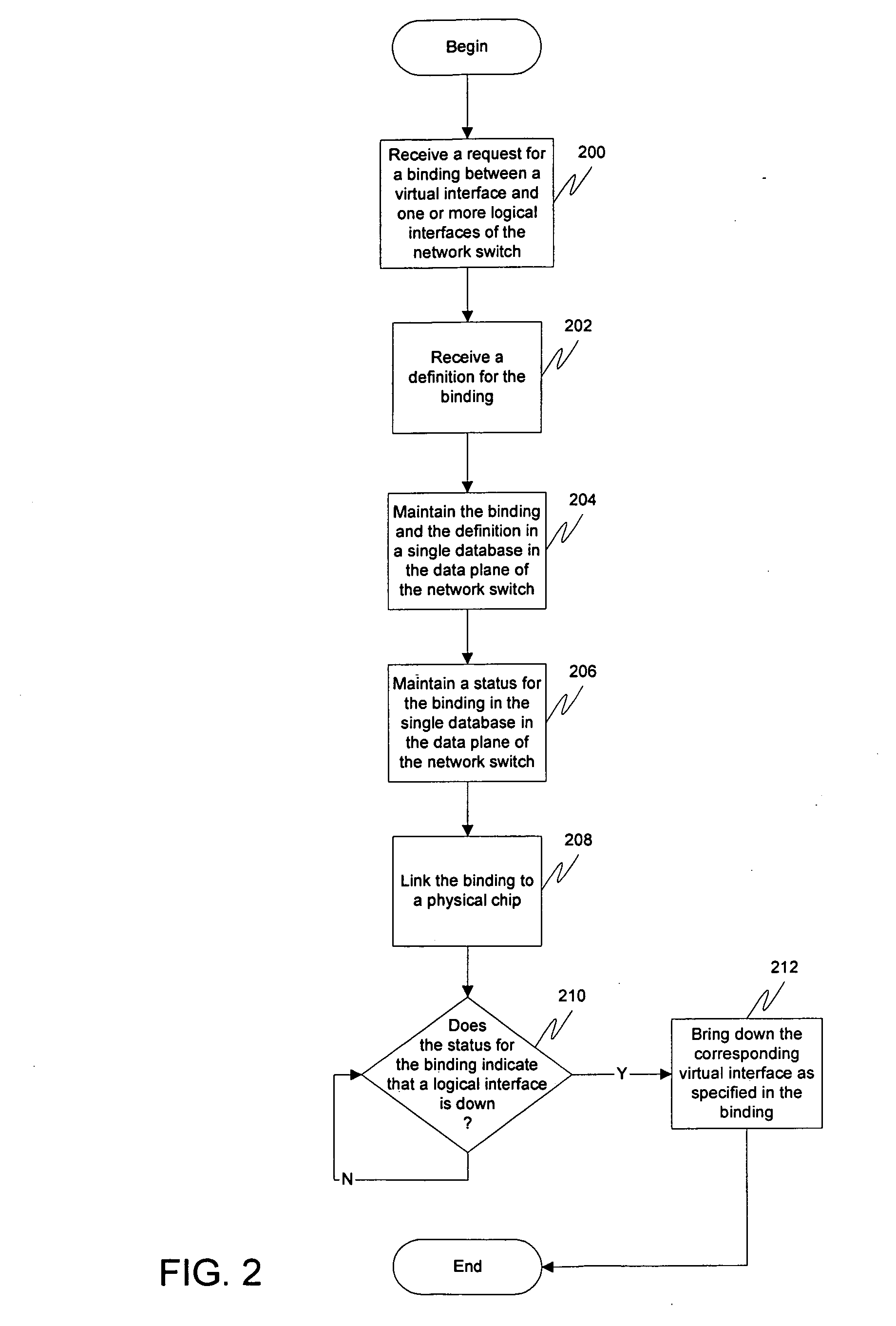
[0019] Switching and routing functions may be provided in a data plane of a network switch by having all functions and algorithms needed to handle all related interface, logical and physical, under one interface manager to keep track of bindings between virtual interfaces and logical interfaces, as well as maintain the statuses of ports that belong to the virtual interface and the actual logical ports. When the actual interface goes down, the virtual interface may go down along with it. The bindings may also include definitions. All of these bindings may be located in a single routing information base (RIB) database, eliminating the need for multiple bindings to be kept in various places. Furthermore, a hardware abstraction layer in the control plane can also then be mirrored in the data plane, eliminating the need for the customer to create a layer performing the same tasks.

Problems solved by technology

As a result, it takes longer to resolve packet destinations in a router than it does in a switch because the Ethernet frame has to be stripped out before the IP packet is processed.
The main drawback of these systems, however, comes in their design stage.
Placing this much burden on the designers of a switch increases their development costs as well as development time.
Traditionally, these functions are performed ad-hoc without any consideration as to the interrelationships between the abstracted functions, in many cases creating unnecessary duplication of functions, data structures, and communication paths.
Thus, the design burden for all of these components is placed on the customer.

Method used


Image

  • Hardware abstraction layer
  • Hardware abstraction layer
  • Hardware abstraction layer

Examples


Embodiment Construction

[0023] Embodiments of the present invention are described herein in the context of a system of computers, servers, and software. Those of ordinary skill in the art will realize that the following detailed description of the present invention is illustrative only and is not intended to be in any way limiting. Other embodiments of the present invention will readily suggest themselves to such skilled persons having the benefit of this disclosure. Reference will now be made in detail to implementations of the present invention as illustrated in the accompanying drawings. The same reference indicators will be used throughout the drawings and the following detailed description to refer to the same or like parts.

[0024] In the interest of clarity, not all of the routine features of the implementations described herein are shown and described. It will, of course, be appreciated that in the development of any such actual implementation, numerous implementation-specific decisions must be made...


PUM


Abstract

Switching and routing functions may be provided in a data plane of a network switch by having all functions and algorithms needed to handle all related interface, logical and physical, under one interface manager to keep track of bindings between virtual interfaces and logical interfaces, as well as maintain the statuses of ports that belong to the virtual interface and the actual logical ports. When the actual interface goes down, the virtual interface may go down along with it. The bindings may also include definitions. All of these bindings may be located in a single routing information base (RIB) database, eliminating the need for multiple bindings to be kept in various places. Furthermore, a hardware abstraction layer in the control plane can also then be mirrored in the data plane, eliminating the need for the customer to create a layer performing the same tasks.

Description

CROSS-RELATION TO RELATED APPLICATION [0001] This application claims priority based on Provisional Application Ser. No. 60 / 656,756, entitled “Hardware Abstraction Layer” by Vividh Siddha, Kunihiro Ishiguro and Willie Hernandez, filed on Feb. 25, 2005.FIELD OF THE INVENTION [0002] The present invention relates to the network switches. More specifically, the present invention relates to a hardware abstraction layer for use in a network switch architecture. BACKGROUND OF THE INVENTION [0003] A network switch is a hardware device for making and breaking a data connection between two endpoints. Switches may be employed to crate a virtual circuit between pairs of endpoints, fulfilling a role similar to that of a router in a connectionless network by diverting data packets toward their intended destination. [0004] Switches traditionally have two software planes: a control plane and a data plane. The control plane is the portion of the system responsible for providing the actual functions a...

Claims


Application Information

Patent Timeline
IPC IPC(8): H04L12/28H04L12/56
CPCH04L45/245H04L49/604H04L49/70
Inventor SIDDHA, VIVIDHISHIGURO, KUNIHIROHERNANDEZ, GUILLERMO A.
Owner IP INFUSION INC
Learn More