Chuck

a technology of chuck and chuck body, which is applied in the field of chuck, can solve the problems of incompatibility of the chuck described above and the above-discussed chuck, and the inability to guide with the required concentric precision,

Inactive Publication Date: 2006-08-31
HILTI AG
View PDF3 Cites 21 Cited by
  • Summary
  • Abstract
  • Description
  • Claims
  • Application Information

AI Technical Summary

Benefits of technology

[0017] Advantageously, the guide members are located radially outwardly of the guide diameter by at least 0.1 mm in a rotational position of the clamping sleeve. As a result, during the percussion boring, the guide members are not subjected to wear by the percussion borer which reciprocates in the receiving sle

Problems solved by technology

In such chucks, the rotary borer, such as a wood or metal borer, which is received with its shank in the chuck and which is not secured with a possibility of a limited axial displacement, cannot be guided with a required concentric precision only with susceptible to wear receiving s

Method used


Image

  • Chuck
  • Chuck
  • Chuck

Examples


Embodiment Construction

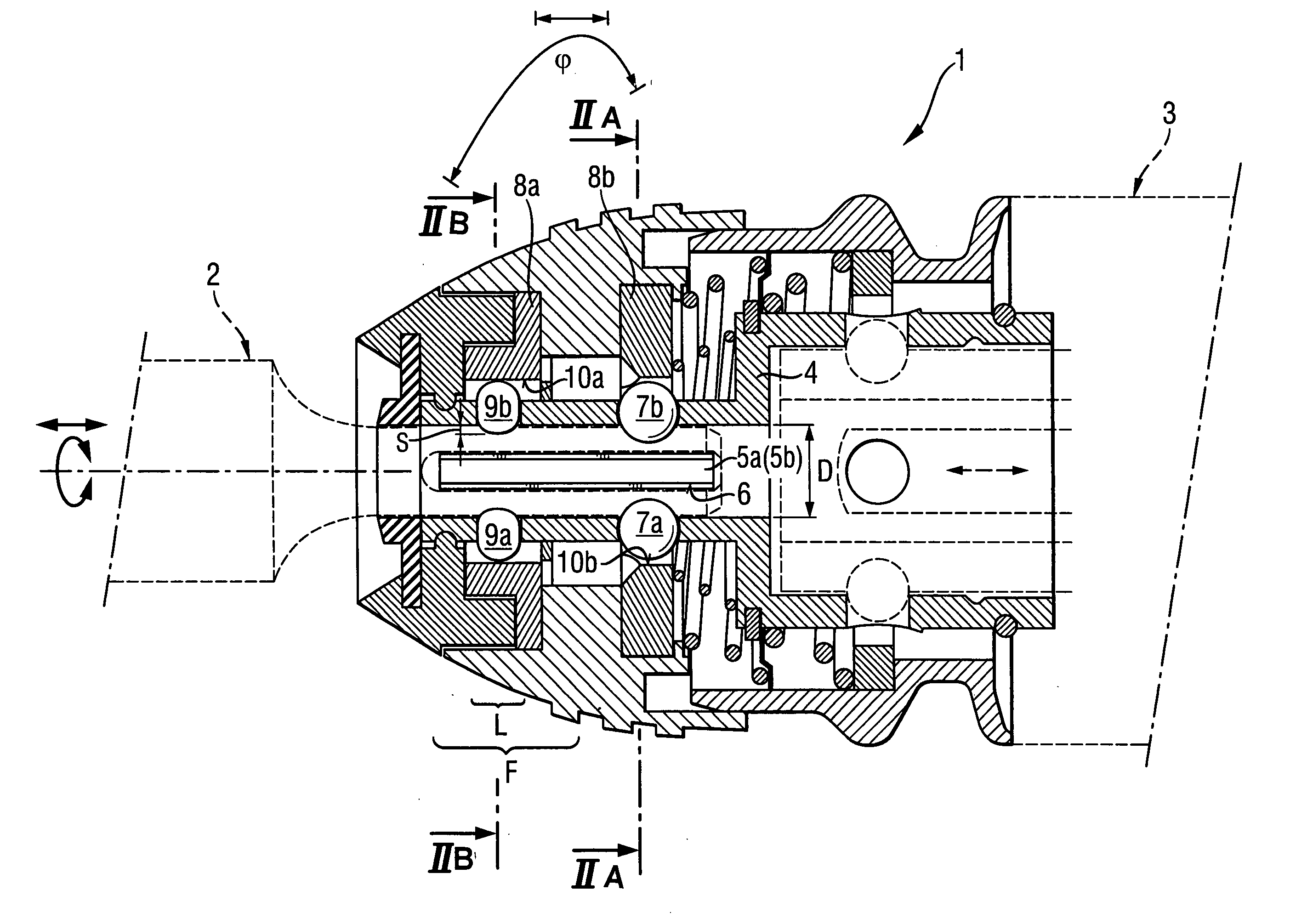
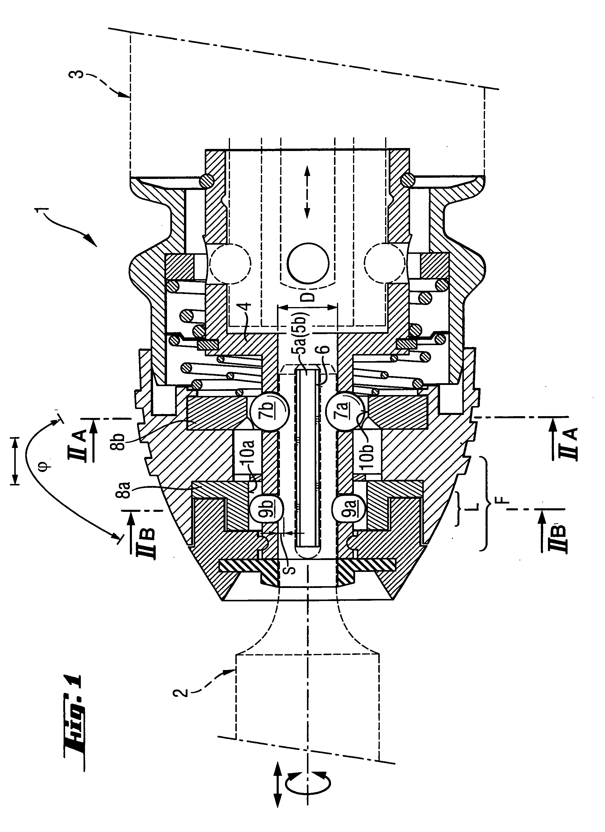
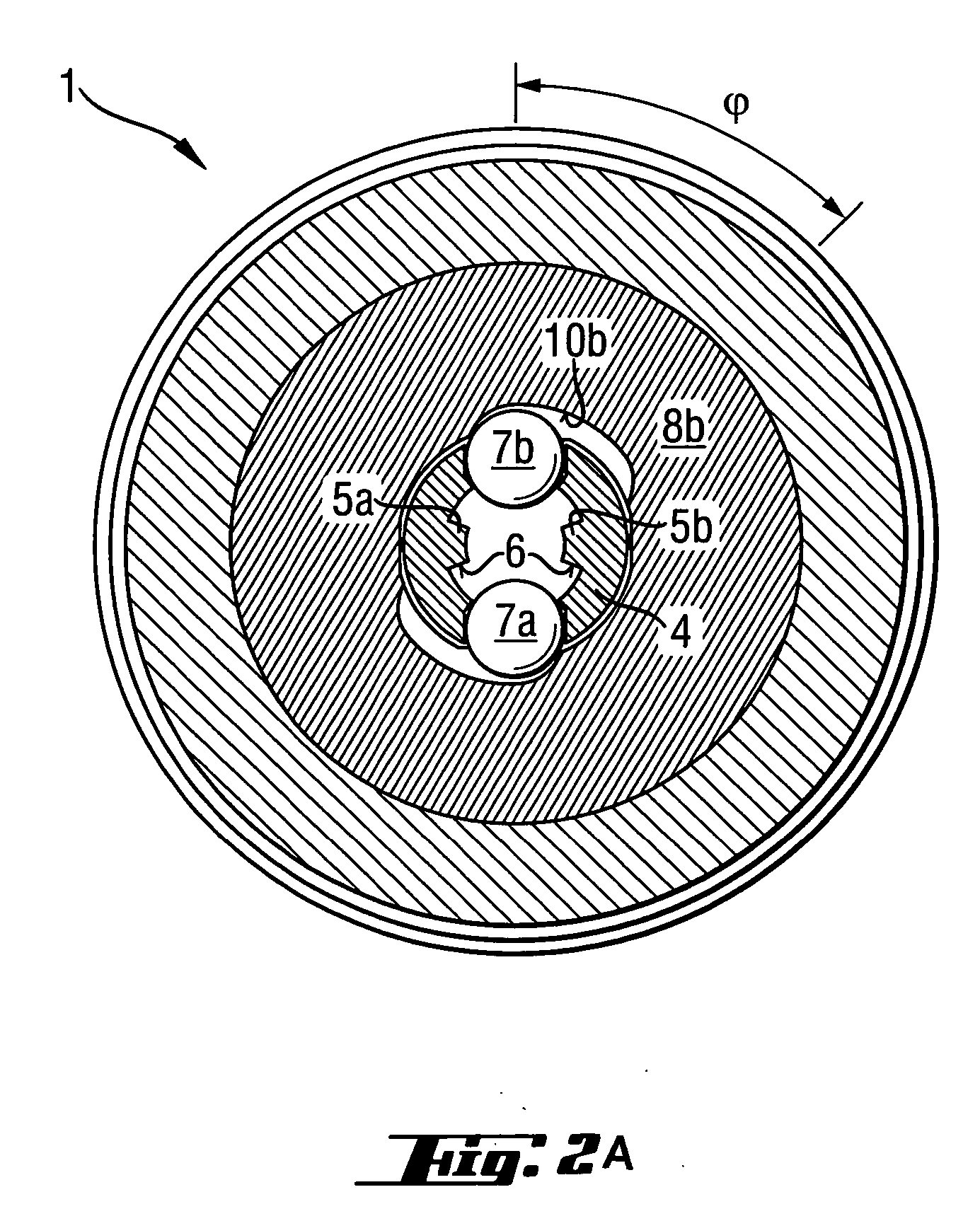
[0029] A chuck 1 according to the present invention for receiving a rotary-percussion working tool 2 driven by a power tool 3, which is shown in FIGS. 1, 2a, and 2b, includes two, located directly opposite each other, strip-shaped rotation-transmitting webs 5a, 5b projecting radially inward from a hollow cylindrical receiving sleeve 4 having a guide diameter D, and two, radially displaceable locking members 7a, 7b that are formed as balls. The rotation-transmitting webs 5a, 5b have respective radially extending contact surfaces 6. In the receiving sleeve 4, in the working tool-side region F of the guide diameter D, there are provided, between the two rotation-transmitting webs 5a, 5b, two guide members 9a, 9b which are displaceable radially inwardly with a rotatable, externally operated, first clamping sleeve 8a. The guide members 9a, 9b are formed as segments of hollow cylinders the axial guide length of which amounts to a half of the guide diameter D of the receiving sleeve 4. In ...


PUM


Abstract

A chuck for receiving a working tool driven by a power tool includes a hollow cylindrical sleeve (4) for receiving the working tool (2), strip-shaped, rotation-transmitting webs (5a, 5b) projecting radially inward from the receiving sleeve (4), at least one radially displaceable locking member (7a); at least two guide members (9a, 9b) provided in a working tool-side guide region (F) of the guide diameter (D) of the receiving sleeve and spaced from the rotation-transmitting webs (5a, 5b), and a manually rotatable clamping sleeve (8a) for displacing the guide members (9a, 9b) radially inwardly.

Description

BACKGROUND OF THE INVENTION [0001] 1. Field of the Invention [0002] The present invention relates to a chuck with radially displaceable locking members, in particular, for a combination hammer drill for receiving a percussion or a rotary borer. [0003] 2. Description of the Prior Art [0004] Percussion and rotary working tools have a shank with which the tool is formlockingly received in a chuck for joint rotation therewith and for limited axial displacement relative thereto. The tool is axially secured with at least one radially displaceable locking member extendable in a groove formed in the shank and closed at its power tool-side end. [0005] German Publications DE 19724532 and DE 3205063 both disclose a chuck having a hollow cylindrical receiving sleeve having a guide diameter and strip-shaped rotation-transmitting web projecting radially inward, and a radially displaceable locking member. [0006] Practically standardized shanks and associated chucks, which are presently used worldw...

Claims


Application Information

Patent Timeline
IPC IPC(8): B23B31/00
CPCB23B2231/44Y10T279/17068B25D2217/0042B25D17/088
Inventor KLEINE, WERNERBRITTEN, WERNER
Owner HILTI AG
Why Eureka
Try Eureka