Automated system for detection and control of water leaks, gas leaks, and other building problems

a technology for automatic system and water leak detection, applied in the direction of fluid leakage detection, fluid tightness measurement, instruments, etc., can solve the problems of undesirable water, gas or other substances entering the building, occupants' health hazards, and parts of these networks that require periodic maintenan

Inactive Publication Date: 2006-08-31
GARABEDIAN MICHAEL +1
View PDF2 Cites 39 Cited by
  • Summary
  • Abstract
  • Description
  • Claims
  • Application Information

AI Technical Summary

Benefits of technology

[0024] According to another aspect of the invention, the control device is used to reset alarms and valves. The control device includes multiple switches for independent operation of valves and alarms. Thus, an alarm may be deactivated without the need to reopen a valve closed to prevent a leak.

Problems solved by technology

The parts in these networks often require periodic maintenance.
Not infrequently, there is a malfunction and undesirable water, gas or other substances leak into the building.
These leaks present a health hazard to the occupants and cause significant damage to the building and its contents.
Often, the occurrence of a leak is not noticed until sufficient water or other substance has accumulated in an occupied area.
Since the network of pipes is generally located out of sight, a substantial leak, with accompanying damage, will have occurred before its occurrence is detected.
Failures also occur at the fixture or appliance which also may cause a leak.
Failures within the network are often caused by ambient conditions which cause the water in certain pipes, such as pipes extending through or along poorly-insulated outside walls, to freeze, bursting the pipes.
Serious flooding is also often caused by inadvertently leaving a faucet in a sink or tub running with the associated drain blocked.
Additionally, in buildings which are heated, there is a constant danger that lethal carbon monoxide will be generated from improper combustion of the fuel source.
While the locations of potential leaks can be determined, some of these locations, such as the places where pipes run through or near exterior walls, are not easily accessed.
However, this method requires hard wired connections to each area in which leaks are to be sensed.
In general, many of such locations cannot be easily reached with wiring.
Furthermore, when a water leak is detected, this method lacks a way to determine which location is affected.
With this sensor, leaking water may not always establish contact with all exposed areas of the insulated conductors, or that leaking water may not adhere to the conductors, thereby obviously failing to signal a leak.
An alarm actuating circuit is interconnected with the conductors and configured to initiate an alarm when water bridges the closely spaced conductors, It appears that this apparatus is insensitive to small leaks because water droplets are unable to bridge the sensing electrode gap disposed on the opposite sides of the sensor assembly.
This device suffers from being susceptible to malfunctions due to corrosion, hard water, and the like, and from being dependent upon a fine temperature differential, that, in turn, requires a high sensitivity which is inherently adversely affected by the thermistor itself Furthermore, in order to obtain reasonable leak detection performance over a protracted period of time, the device must be calibrated from season to season.
A leak detected at any of the sensors causes the control device to shut off the liquid or gas flow.
One of the difficulties with the system disclosed in Diduck is that once the valve is shut off, the location of the leak remains unknown.
While many different sensor and control systems are known and disclosed in the patent literature, none of such systems provide complete protection under a variety of conditions.
Nevertheless, known systems are limited to a single predetermined response to all detected conditions.
They cannot provide alternative responses based upon the type or location of a sensor detecting a leak.

Method used


Image

  • Automated system for detection and control of water leaks, gas leaks, and other building problems
  • Automated system for detection and control of water leaks, gas leaks, and other building problems
  • Automated system for detection and control of water leaks, gas leaks, and other building problems

Examples


Embodiment Construction

[0031] The present invention is a “smart” system allowing multiple possible responses to detection of leaks. In prior art systems, only a single prescribed response was possible. The response could include multiple actions, such as activating an alarm and shutting off a valve, but such systems could not selective perform actions. Thus, prior art systems were limited to implementations which protected against a single type of leak. Such a system cannot provide the flexibility necessary for a complete protection system or for multiunit buildings. The present invention provides greater flexibility through selection of responses based upon the type and location of detected leaks.

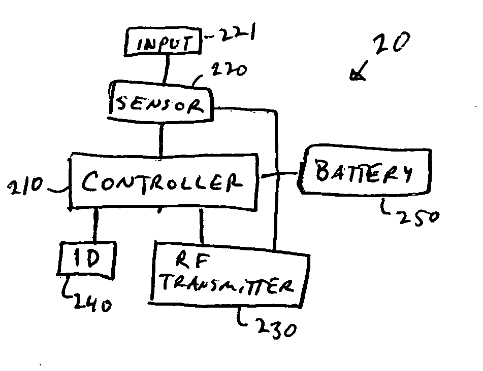
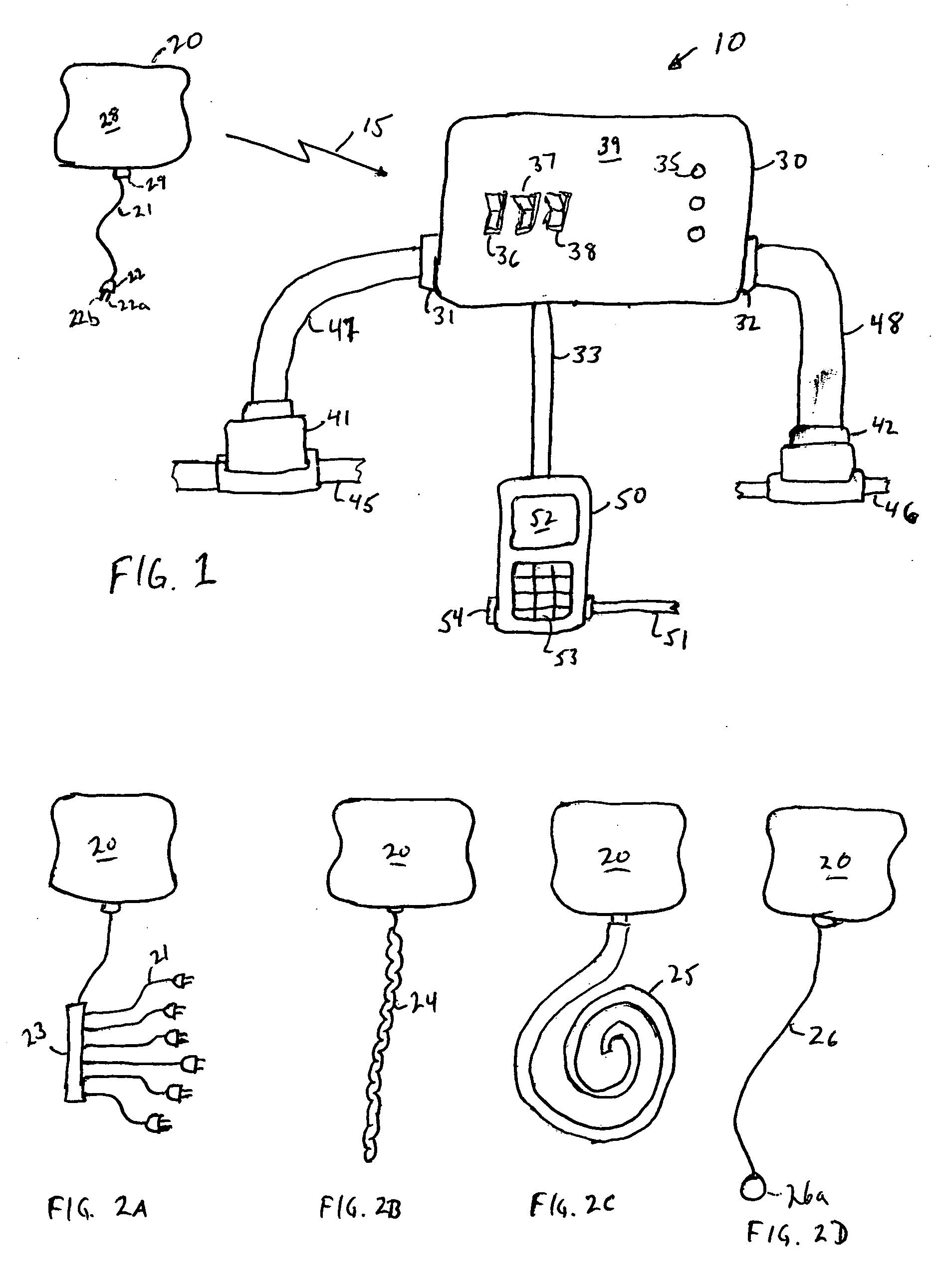
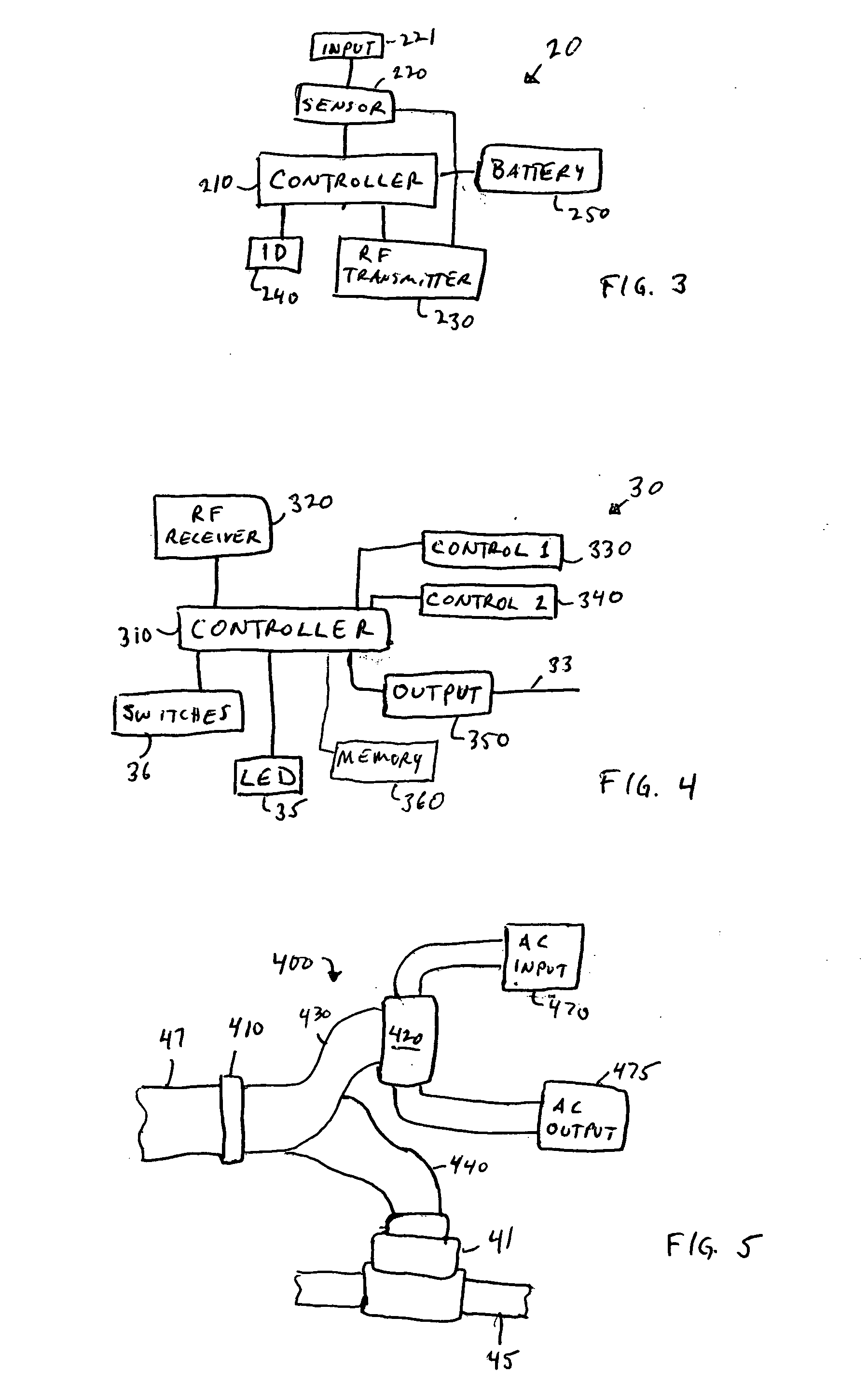
[0032] According to an embodiment of the invention illustrated in FIG. 1, the system 10 includes two types of devices, a plurality of sensors 20 (one shown) and a controller 30. The sensors 20 are placed at locations of possible leaks. The controller 30 is placed remotely from the sensors and preferably at loca...


PUM


Abstract

A leak detection system performs actions based upon the type and location of the detected leak. A plurality of sensors and sensor types are used at various locations in a building where leaks are likely to occur. Upon detection of a leak, a sensor transmits an RF signal identifying the sensor. A controller receives the RF signal and performs actions associated with the identifier for the sensor. Actions may include selectively closing or opening valves and electrical connections. Notifications are also sent by the system to building owners or occupants.

Description

BACKGROUND OF THE INVENTION [0001] 1. Field of the Invention [0002] The present invention relates to a system for detecting water leaks, gas leaks and other building problems and automatically acting to prevent significant damage. More particularly, it relates to a system for monitoring multiple locations and selective control of building devices based upon detected leak locations. [0003] 2. Discussion of Related Art [0004] Buildings include networks pipes, valves, and other mechanized devices for conveying liquids and / or gases, such as water, oil, natural gas, and propane. The parts in these networks often require periodic maintenance. Not infrequently, there is a malfunction and undesirable water, gas or other substances leak into the building. These leaks present a health hazard to the occupants and cause significant damage to the building and its contents. The type and location of a malfunction or failure cannot be predetermined. Thus, in order to limit damage and the safety haz...

Claims


Application Information

Patent Timeline
IPC IPC(8): G01M3/04
CPCF17D5/06
Inventor GARABEDIAN, MICHAELGARABEDIAN, PATRICK
Owner GARABEDIAN MICHAEL
Why Eureka
Try Eureka