
Translation generation for a mask pattern

Inactive Publication Date: 2006-08-24
INTEL CORP
View PDF9 Cites 4 Cited by
  • Summary
  • Abstract
  • Description
  • Claims
  • Application Information

AI Technical Summary

Problems solved by technology

One problem currently faced by IC manufacturers is the problem of mask defects (herein “defects”) that may be present in the patterned masks.
These defects include multilayer defects that are embedded within the mask itself.
The presence of defects may produce unwanted shadows and / or dispersion of the exposure radiation, which may reduce manufacturing yields.
Unfortunately, removing defects that are present in the masks is often extremely difficult, particularly multilayer defects.

Method used


Image

  • Translation generation for a mask pattern
  • Translation generation for a mask pattern
  • Translation generation for a mask pattern

Examples


Embodiment Construction

[0023] In the following description, for purposes of explanation, numerous details are set forth in order to provide a thorough understanding of the disclosed embodiments of the present invention. However, it will be apparent to one skilled in the art that these specific details are not all required in order to practice the disclosed embodiments of the present invention.

[0024] The following description includes terms such as on, onto, on top, underneath, underlying, downward, lateral, and the like, that are used for descriptive purposes only and are not to be construed as limiting. That is, these terms are terms that are relative only to a point of reference and are not meant to be interpreted as limitations but are, instead, included in the following description to facilitate understanding of the various aspects of the invention.

[0025] Various operations will be described as multiple discrete operations in a manner that is most helpful in understanding these embodiments; however,...


PUM


Abstract

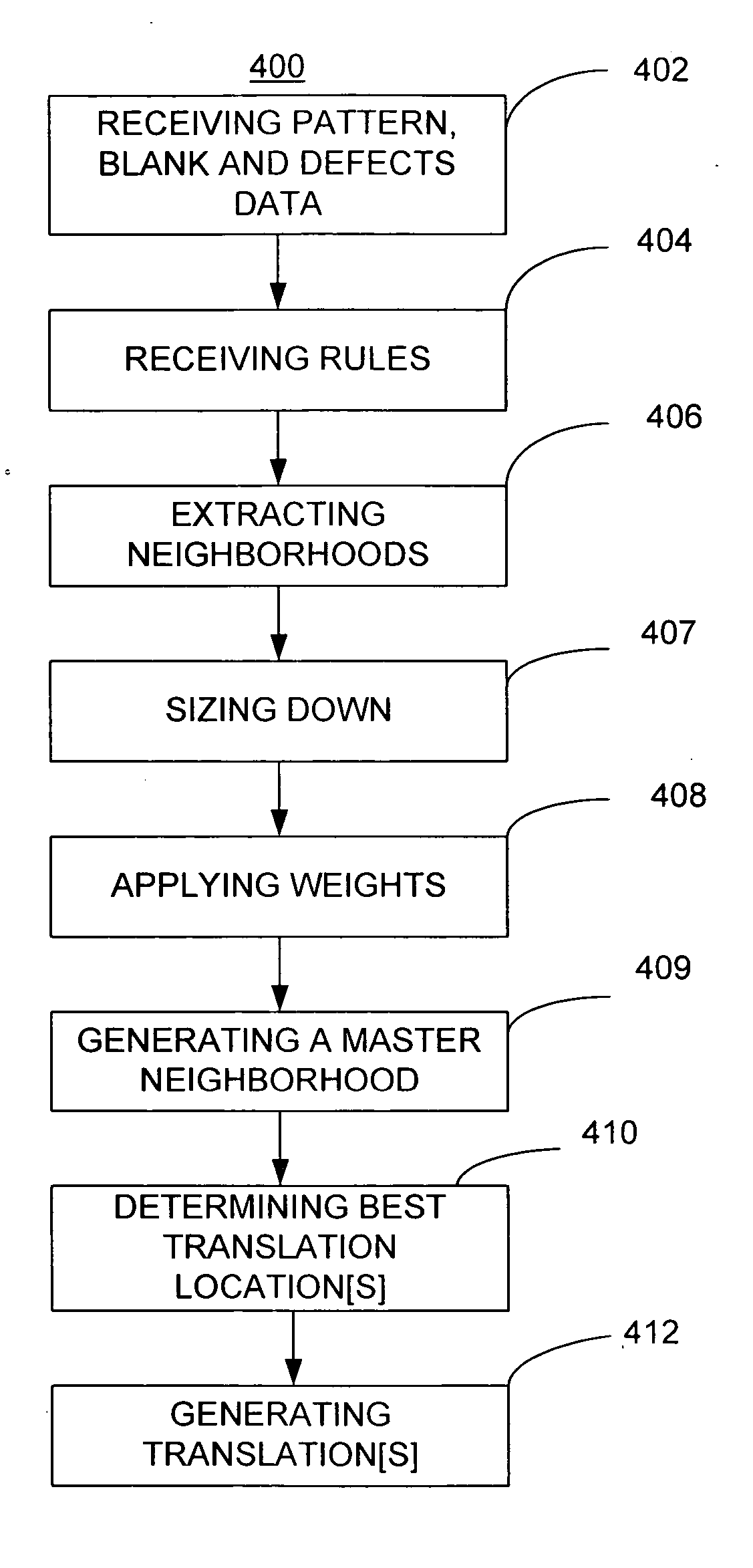
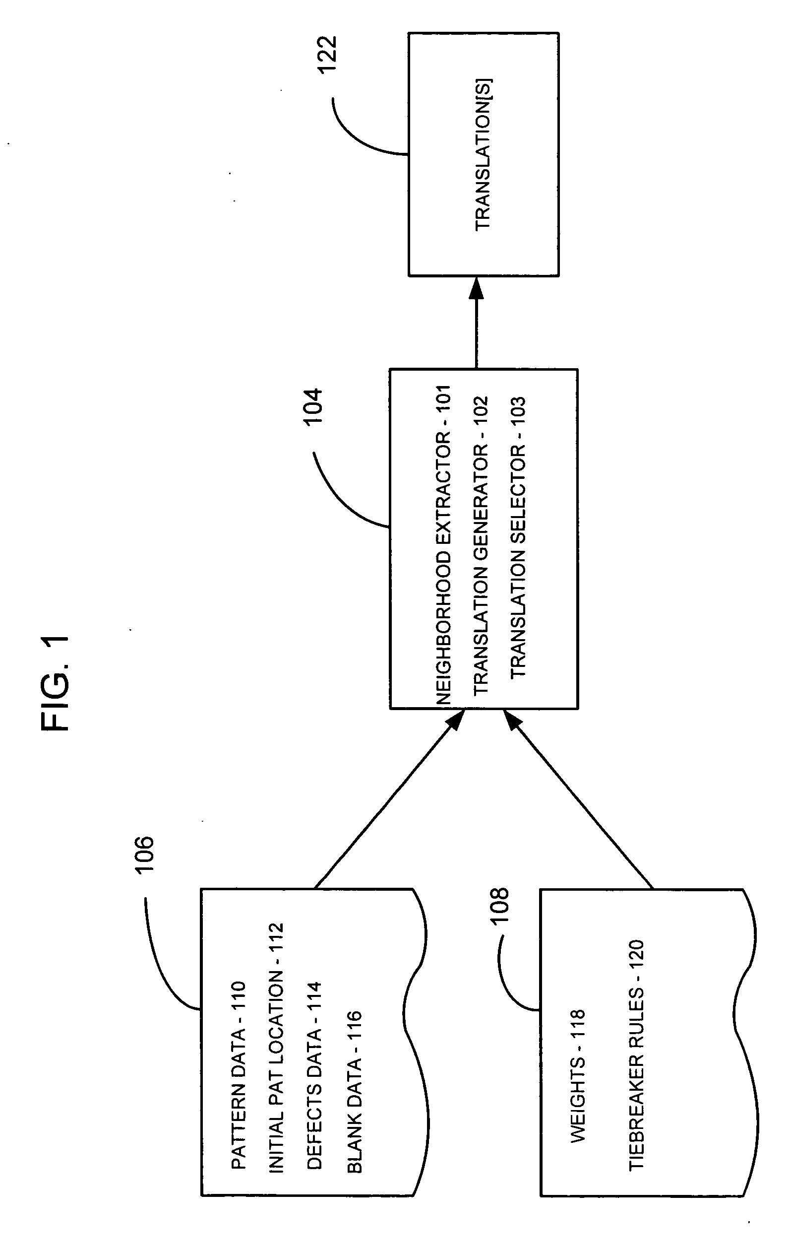
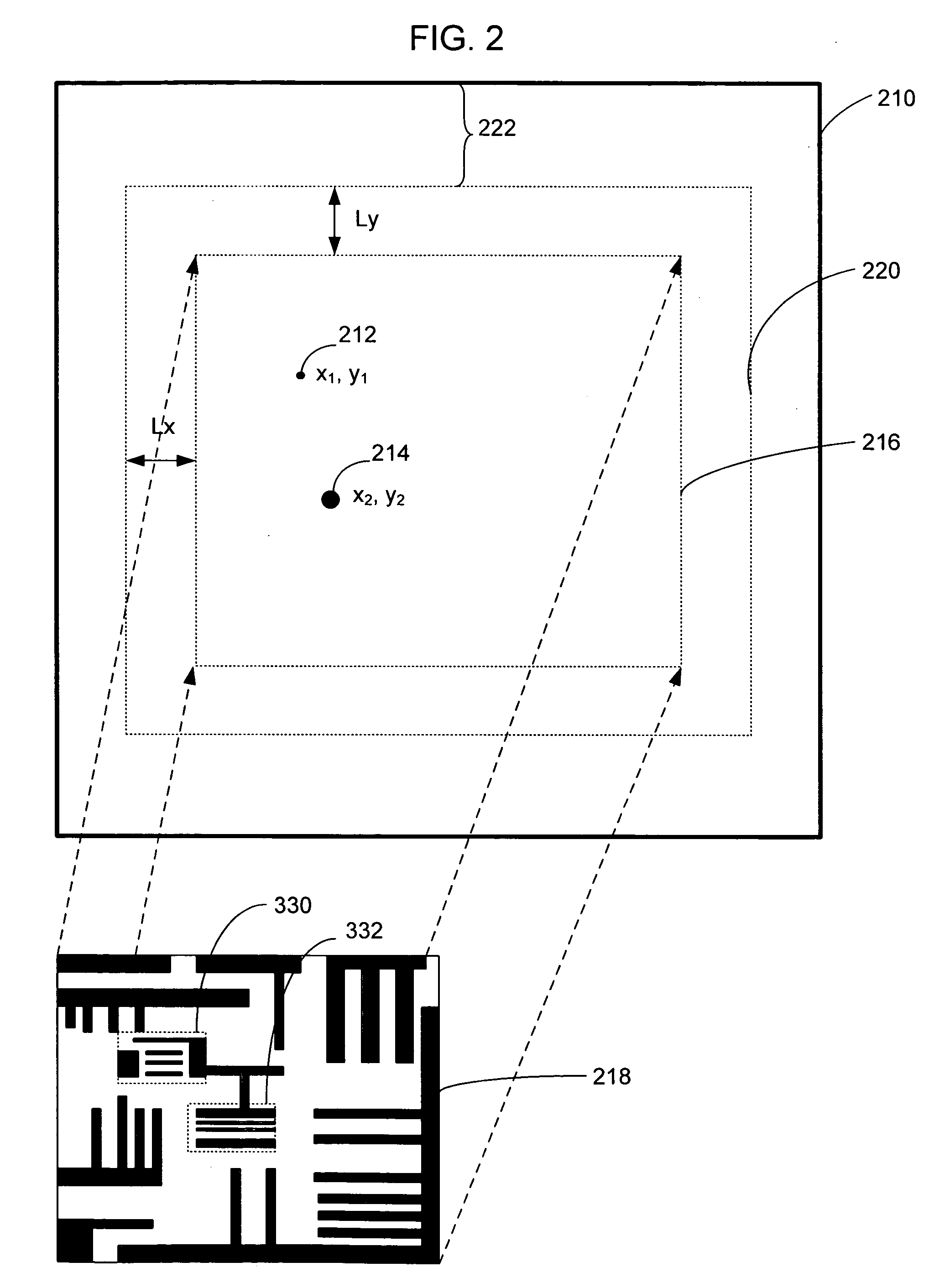
Generation of one or more translations is described. The generated translations may be applied to a mask pattern so that the pattern may be moved to cover one or more mask defects in part or in totality.

Description

BACKGROUND OF THE INVENTION [0001] 1. Field of the Invention [0002] Embodiments of the present invention relate to, but are not limited to, electronic device manufacturing, and in particular, to the field of photolithography employing patterned masks. [0003] 2. Description of Related Art [0004] In the field of integrated circuit (IC) manufacturing, a process known as photolithography is typically employed in order to form circuitry features onto, for example, a silicon wafer. In the process, an exposure operation is performed whereby selective portions of a photoresist film that is disposed on the wafer surface is exposed to electromagnetic radiation. The type of electromagnetic radiation used will depend upon the sizes of the circuitry features being formed. Typically, the smaller the size of the circuitry features being formed, the shorter the wavelengths of the electromagnetic radiation will be. [0005] The current trend is to build IC with smaller and smaller circuitry features. ...

Claims


Application Information

Patent Timeline
IPC IPC(8): G06F17/50
CPCB82Y10/00B82Y40/00G03F1/144G03F1/24G03F1/72
Inventor STIVERS, ALAN R.
Owner INTEL CORP
Learn More