
Gear structure and timepiece having the same

a technology of gear structure and timepiece, applied in the field of gear structure, can solve the problems of difficult attachment and detachment of gear structure, unremovable fixed gear body to the support shaft, and inability to integrate the gear structure with an apparatus and remove the apparatus, etc., and achieve the effect of easy attachment and detachmen

Inactive Publication Date: 2006-08-24
SEIKO INSTR INC
View PDF14 Cites 25 Cited by
  • Summary
  • Abstract
  • Description
  • Claims
  • Application Information

AI Technical Summary

Benefits of technology

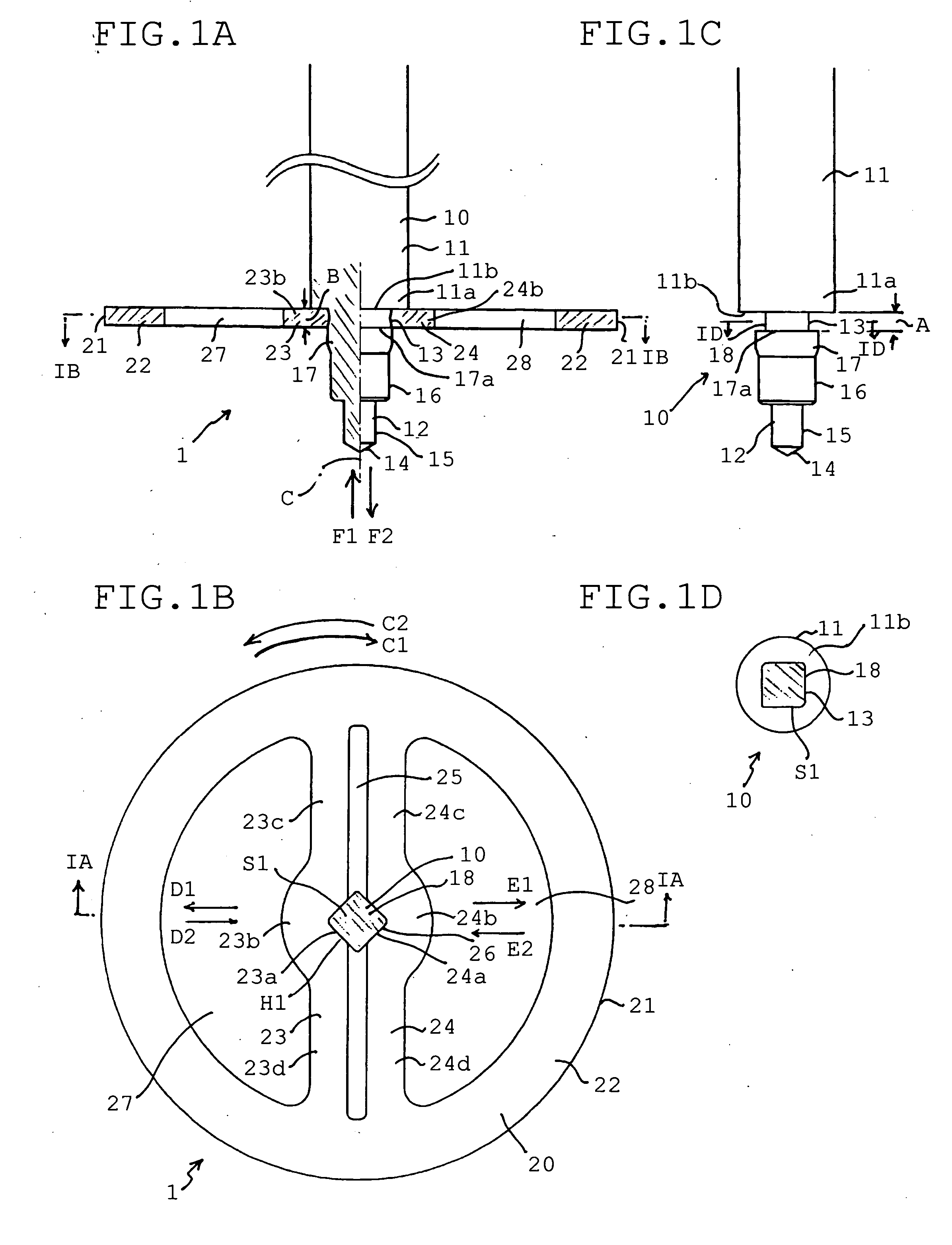
[0016] In this case, the gear main body can easily be attached and detached to and from the support shaft by only elastically deforming the spring portion. In order to elastically deform the spring portion, a previously prepared jig or the like may be used. Further, the fitting portion of the gear main body is provided with the noncircular opening and the support shaft is provided with the fitted shaft portion having the section in the noncircular shape and therefore, by only elastically deforming the fitting portion of the gear main body to be fitted to the fitted shaft portion of the support shaft, the gear portion can be mounted to the support shaft relatively unrotatably. Further, typically, although the noncircular shape of the opening substantially coincides with the noncircular shape of the section of the fitted shaft portion, so far as rotation of the gear main body relative to the support shaft can be prohibited by bringing a noncircular region of the peripheral wall of the opening into contact with a noncircular region of a portion of a peripheral face of the fitted shaft portion, depending on cases, the noncircular shape of the opening may differ from the noncircular shape of the section of the fitted shaft portion. Further, different from the case of slip rotation, it is not necessary to engage the both members by friction and therefore, shapes thereof relative to each other without rattle or play are selected. When the shape of the opening and the shape of the cross-sectional face of the fitted shaft portion are actually the same (similar), strictly, the fitted shaft portion is formed to be slightly larger than the opening such that the gear portion can be supported unmovably by the fitted shaft portion.
[0017] Further, the spring portion is typically constituted by a pair of arm portions extended substantially in a diameter direction to form springs supported by both sides thereof. However, when desired, spring performance may be provided to only one thereof, depending on cases, the spring portion may be constituted by a spring supported by one side thereof. Further, when desired, the spring portion may be constituted by three or more of spring portions. Further, the spring portion is operated in a direction along the extended face of the gear main body.
[0018] According to the gear structure of the invention, typically, cross-sectional faces of the opening and fitted shaft portion include a shape selected from a group consisting of a polygonal shape, an oval shape and a polygonal shape a corner portion of which is rounded. Here, the oval shape includes an elliptical shape, an oval shape in a shape of a track or the like. Although the polygonal shape is typically constituted by a quadrangular shape, the polygonal shape may be a pentagonal shape or a polygonal shape having more angles. Although a quadrangular shape is typically constituted by a quadrate or a rectangular shape, the quadrangular shape may be constituted by an oblong shape. Further, the shapes of the cross-sectional faces of the opening and the fitted portion are typically selected from a viewpoint of easiness in fabricating the gear main body and the support shaft. However, the shapes may be other shapes so far as relative rotation thereof can actually prohibited once fitted.

Problems solved by technology

However, according to the gear structure of the background art, the gear main body is fixed unremovably to the support shaft.
Further, since the support shaft and the gear main body of the gear structure are integrated, integration of the gear structure to an apparatus and removal from the apparatus, that is, attachment and detachment of the gear structure is not easy.

Method used


Image

  • Gear structure and timepiece having the same
  • Gear structure and timepiece having the same
  • Gear structure and timepiece having the same

Examples


Embodiment Construction

[0027] An explanation will be given of a preferable embodiment of the invention based on a preferable embodiment shown in the attached drawings.

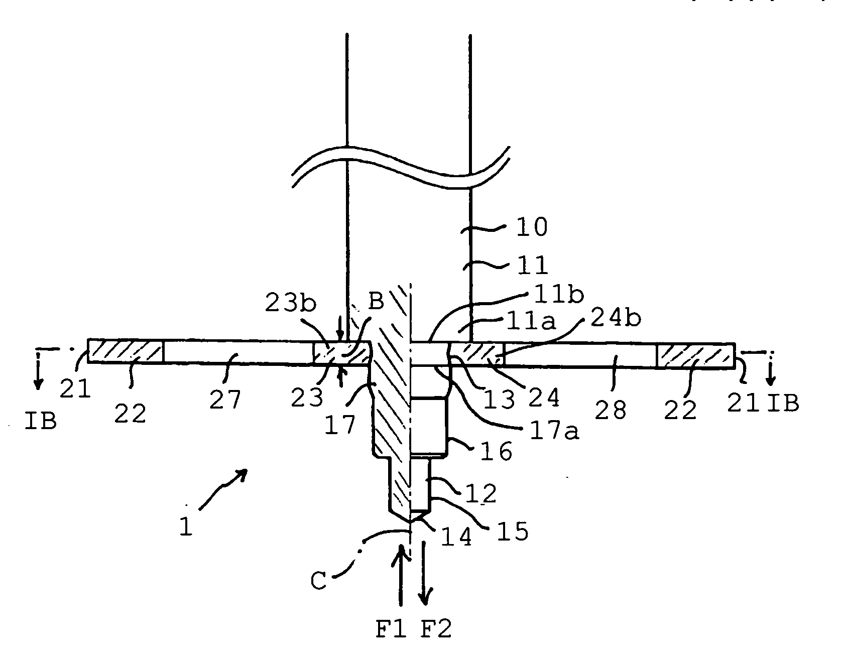
[0028] As shown by FIGS. 1A and 1B, a gear structure 1 of a preferable embodiment according to the invention is provided with a support shaft 10 and a gear main body 20.

[0029] As shown by FIGS. 1C and 1D, the support shaft 10 is provided with a shaft main body portion 11 in a shape of a circular pillar, a fitted axially supported end portion 12 at one end, and a fitted shaft portion 13 fitted with the gear main body 20. Further, a fitted axially supported end portion (not illustrated) similar to the fitted axially supported end portion 12 is formed also at the other end side of the shaft main body portion 11.

[0030] According to the example, the fitted axially supported end portion 12 includes a tenon 15 in a mode of a small diameter circular pillar shape portion supported by a bearing (not illustrated) such as a jewel. According to the ex...


PUM


Abstract

To provide a gear structure easy to be attached and detached and a timepiece having the same. A gear structure includes a support shaft having a fitted shaft portion and a gear main body having fitting portions elastically fitted to the fitted shaft portion. The fitting portion of the gear main body and the fitted shaft portion of the support shaft are constituted such that the fitting portion of the gear main body is fitted to the fitted shaft portion of the support shaft in a state of prohibiting rotation of the gear main body relative to the support shaft. The fitting portion of the gear main body is constituted to be attachable and detachable to and from the fitted portion of the support shaft by being elastically deformed in D1, E1 and D2, E2 directions. The fitted shaft portion is provided with a noncircular sectional shape shifted from a circle centering on a rotation center axis line of the gear structure, and the fitting portion of the gear main body is provided with a noncircular opening fitted to the fitted portion of the support shaft, and spring portions constituting portions of a peripheral wall of the opening and elastically deformable in a diameter direction of the gear main body.

Description

BACKGROUND OF THE INVENTION [0001] 1. Field of the Invention [0002] The present invention relates to a gear structure suitable for being used in a small-sized precision machine such as a timepiece and a timepiece having the same. [0003] 2. Description of the Prior Art [0004] A gear structure constituted by fitting a gear main body to a support shaft is well known. However, according to the gear structure of the background art, the gear main body is fixed unremovably to the support shaft. [0005] Therefore, according to the gear structure of the background art, even when damage (brake, warp or the like) deteriorating a function is brought about at only one of the support shaft and the gear main body, it is necessary to interchange a total of the gear structure. Further, since the support shaft and the gear main body of the gear structure are integrated, integration of the gear structure to an apparatus and removal from the apparatus, that is, attachment and detachment of the gear stru...

Claims


Application Information

Patent Timeline
Patent Type & Authority Applications(United States)
IPC IPC(8): G04B29/00
CPCG04B13/026G04B13/023
Inventor MURAZUMI, TAKUYA
Owner SEIKO INSTR INC
Learn More