
High throughput endo-illuminator probe

a technology of endoilluminator and probe, which is applied in the field of ophthalmic surgery, can solve the problems of low luminous flux, low illumination efficiency, and low efficiency of wide angle probes, and achieve the effect of high throughput illumination

Inactive Publication Date: 2006-08-17
ALCON INC
View PDF5 Cites 73 Cited by
  • Summary
  • Abstract
  • Description
  • Claims
  • Application Information

AI Technical Summary

Benefits of technology

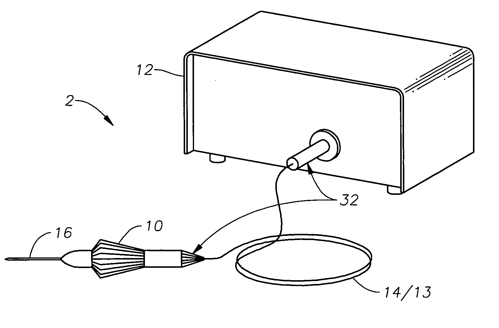
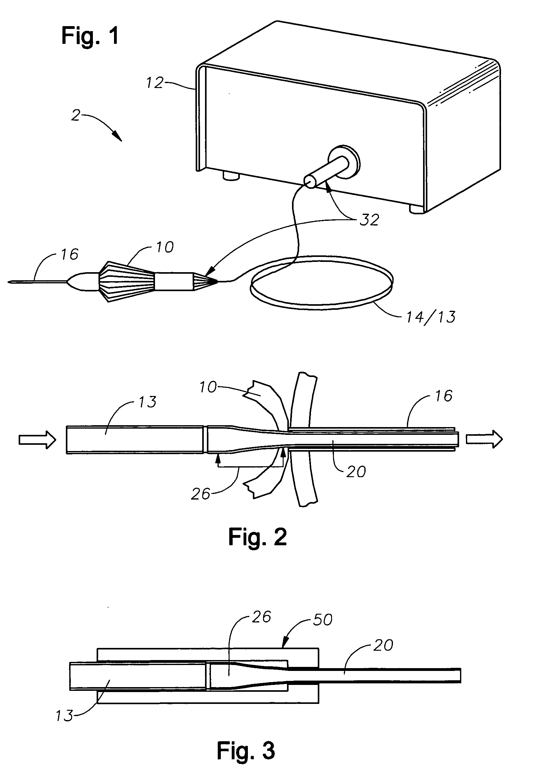
The present invention is a high throughput endo-illuminator that meets the needs of ophthalmic surgery and other surgical procedures. It consists of a light source, a proximal optical fiber, a distal optical fiber, a cannula, and a handpiece. The distal optical fiber has a tapered section with a larger diameter at the proximal end and a smaller diameter at the distal end. The tapered section matches the diameter of the proximal optical fiber at the point of optical coupling. The distal optical fiber is operably coupled to the handpiece, allowing for linear displacement of the fiber within the cannula. The angle of illumination and the amount of illumination can be adjusted by adjusting the linear displacement of the fiber. The high throughput endo-illuminator is designed to improve the efficiency of transmitting light from the light source to the surgical field.

Problems solved by technology

However, these illuminators are subject to an illumination angle vs. luminous flux tradeoff, in which the widest angle probes typically have the least throughput efficiency and the lowest luminous flux (measured in lumens).
Therefore, the resultant illuminance (lumens per unit area) of light illuminating the retina is often lower than desired by the ophthalmic surgeon.
An ultra-flexible thin-walled cannula makes it difficult for the surgeon to do this.
Therefore, a large portion of light from the focused light source beam spot will not enter the smaller diameter fiber and will be lost.
Therefore, the fiber cannot confine the entire beam within the fiber core downstream of the taper.
Instead, a portion of the light source beam (the highest off-axis angle rays) escapes from the core into the cladding surrounding the fiber and is lost.
As a result of these disadvantages, the throughput of the fiber is much less than that of a typical 20 gauge compatible fiber (on average, less than 35% that of the 20 gauge compatible fiber).
Therefore, a large portion of light from the focused light source beam spot will not enter the 0.157 inch diameter fiber and will be lost.
Therefore, a large portion of the light that is focused into the fiber will not propagate through the fiber core and will instead escape the core and pass into the cladding and be lost.
Combined, these two disadvantages result in a fiber throughput that is on average less than 25% that of a typical 20 gauge compatible fiber.
A further disadvantage of prior art small-gauge (e.g., 25 gauge) illuminators is that they are typically designed to emit transmitted light over a small angular cone (e.g., ˜30 degree half angle and ˜22 degree half angle, respectively, for the two prior art examples above).

Method used


Image

  • High throughput endo-illuminator probe
  • High throughput endo-illuminator probe
  • High throughput endo-illuminator probe

Examples


Embodiment Construction

[0031] Preferred embodiments of the present invention are illustrated in the FIGURES, like numerals being used to refer to like and corresponding parts of the various drawings.

[0032] The various embodiments of the present invention provide for a higher gauge (e.g., 20 and / or 25 gauge compatible) optical fiber based endo-illuminator device for use in surgical procedures, such as in vitreo-retinal / posterior segment surgery. Embodiments of this invention can comprise a handpiece, such as the Alcon-Grieshaber Revolution-DSP™ handpiece sold by Alcon Laboratories, Inc., of Fort Worth, Tex., operably coupled to a cannula, such as a 25 gauge cannula. The inner dimension of the cannula can be used to house a distal optical fiber, tapered in accordance with the teachings of this invention. Embodiments of the high throughput endo-illuminator can be configured for use in the general field of ophthalmic surgery. However, it is contemplated and it will be realized by those skilled in the art tha...


PUM

PropertyMeasurementUnit
diameteraaaaaaaaaa
diameteraaaaaaaaaa
diameteraaaaaaaaaa

Abstract

A high throughput endo-illuminator and illumination surgical system are disclosed. One embodiment of the high throughput endo-illumination surgical system comprises: a light source for providing a light beam; a proximal optical fiber, optically coupled to the light source for receiving and transmitting the light beam; a distal optical fiber, optically coupled to a distal end of the proximal optical fiber, for receiving the light beam and emitting the light beam to illuminate a surgical site, wherein the distal optical fiber comprises a tapered section having a proximal-end diameter larger than a distal-end diameter; a handpiece, operably coupled to the distal optical fiber; and a cannula, operably coupled to the handpiece, for housing and directing the distal optical fiber. The tapered section's proximal end diameter can be the same as the diameter of the proximal optical fiber, and can be, for example, a 20 gauge diameter. The tapered section's distal end diameter can be, for example, a 25 gauge compatible diameter. The cannula can be a 25 gauge inner-diameter cannula. The proximal optical fiber can preferably have an NA equal to or greater than the NA of the light source beam and the distal optical fiber preferably can have an NA greater than that of the proximal optical fiber and greater than that of the light source beam at any point in the distal optical fiber (since the light beam NA can increase as it travels through the tapered section).

Description

[0001] The present invention relates generally to surgical instrumentation. In particular, the present invention relates to surgical instruments for illuminating an area during eye surgery. Even more particularly, the present invention relates to a high throughput endo-illuminator probe for illumination of a surgical field. BACKGROUND OF THE INVENTION [0002] In ophthalmic surgery, and in particular in vitreo-retinal surgery, it is desirable to use a wide-angle surgical microscope system to view as large a portion of the retina as possible. Wide-angle objective lenses for such microscope systems exist, but they require a wider illumination field than that provided by the cone of illumination of a typical prior-art fiber-optic illuminator probe. As a result, various technologies have been developed to increase the beam spreading of the relatively incoherent light provided by a fiber-optic illuminator. These known wide-angle illuminators can thus illuminate a larger portion of the reti...

Claims


Application Information

Patent Timeline
Patent Type & Authority Applications(United States)
IPC IPC(8): A61B18/18
CPCA61F9/007A61B90/36A61B2090/306A61B3/0008A61B9/00A61B1/07G02B6/00
Inventor SMITH, RONALD
Owner ALCON INC
Learn More