
Optical measurement instrument for living body

a technology of optical measurement and living body, applied in the field of instruments, can solve the problems of large size, cumbersome handling, and difficult movement of systems, and achieve the effect of satisfactory accuracy and high efficiency

Inactive Publication Date: 2006-08-17
YAMASHITA YUICHI +2
View PDF36 Cites 20 Cited by
  • Summary
  • Abstract
  • Description
  • Claims
  • Application Information

AI Technical Summary

Benefits of technology

"The present invention provides an optical measurement instrument for a living body that can efficiently and accurately measure information on a wide spatial region in a subject. The instrument is small-sized and easy-to-handle, and can perform simultaneous multichannel measurements on multiple measurement positions without crosstalk. It can also measure information on a deep position in a subject with high sensitivity. Additionally, the invention provides high-utility input and control devices by a living body that can control various external equipment with high accuracy by using the measurement signals from the optical measurement instrument."

Problems solved by technology

These systems have drawbacks in that although they have an advantage that the wide region in the living body can be measured as the image information, they are large in size and their handling is cumbersome.
For example, a dedicated room is required to install these systems and the systems are not easy to move as a matter of course.
Further, since persons dedicated to maintenance are required, considerable costs are required for practical use of these systems.
However, in the aforementioned conventional living body measurement technique using the light, the information can be measured only at a specific position in the living body or within a restricted narrow region.
However, in order to successively switch between many incident positions, much time is required correspondingly upon their switching.
Therefore, a long time is required for measurement, so that the measurement is rendered inefficient.
However, there may be cases in which a physically handicapped person encounters difficulties in performing such operations and information input work.
There may also be cases where even a normal person cannot always take quick and appropriate measures in case of emergency of the driving of a vehicle and the operation of a large-scale plant, for example.

Method used


Image

  • Optical measurement instrument for living body
  • Optical measurement instrument for living body
  • Optical measurement instrument for living body

Examples


first embodiment

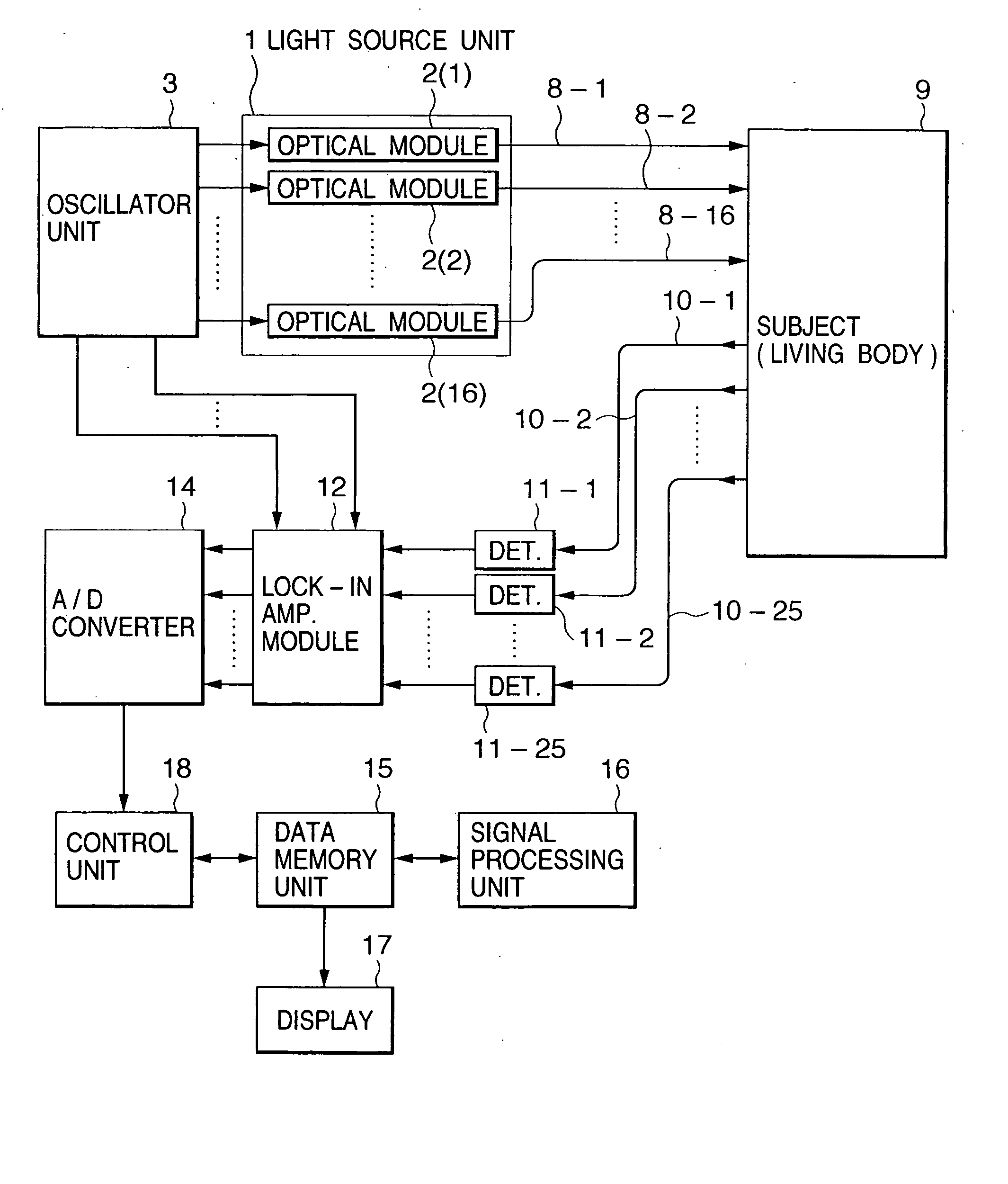
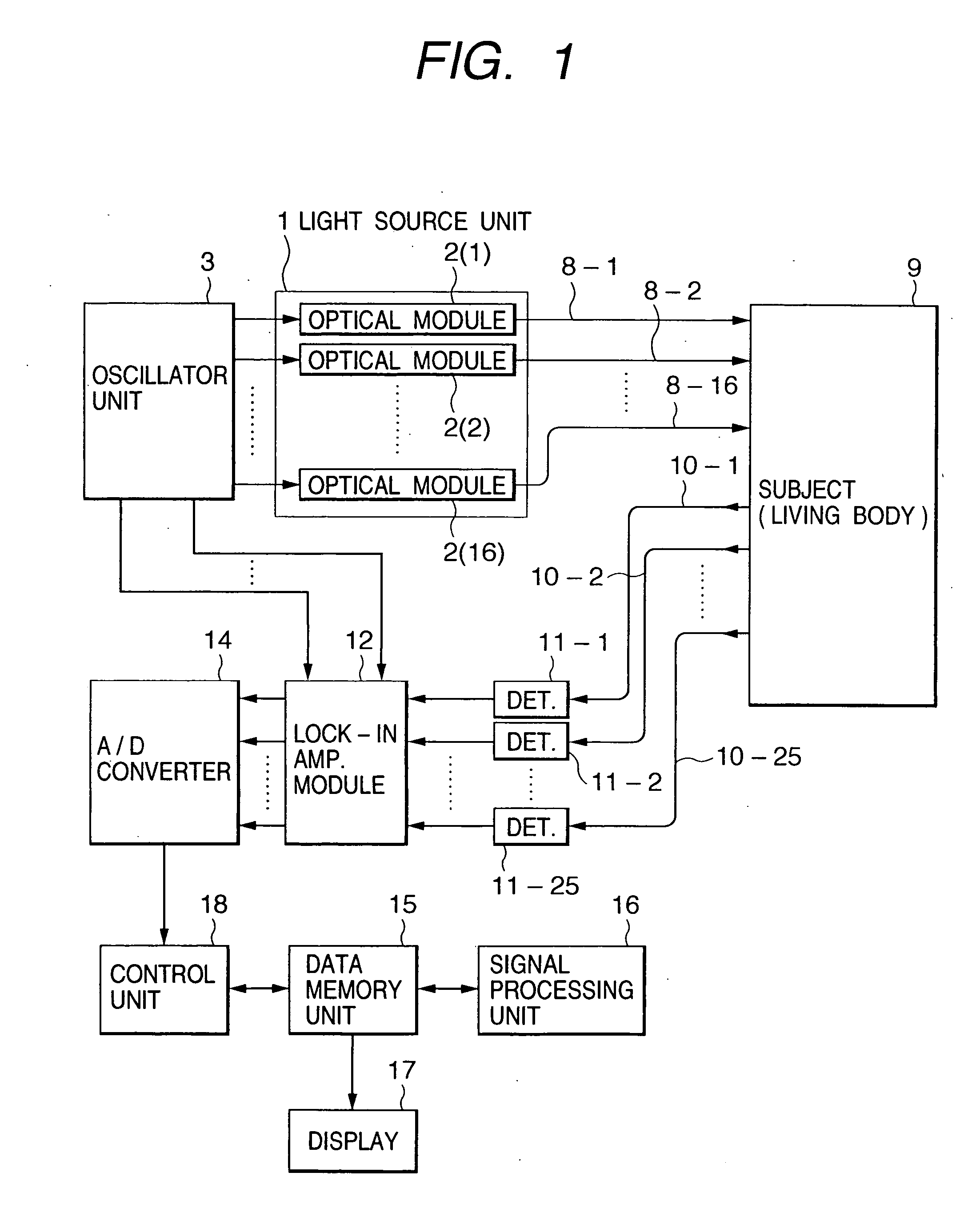
[0070]FIG. 1 schematically illustrates a configuration of an optical measurement instrument for a living body, according to a first embodiment of the present invention.

[0071] The present embodiment shows an instrument configuration wherein the number of measurement channels (i.e., the number of measurement positions) is set to 64 assuming that an inside cerebrum is imaged and measured by applying light to it from above the scarf skin of a human head, for example and detecting the light.

[0072] A light source unit 1 comprises sixteen optical modules 2(1), 2(2), . . . and 2(16). Each of the optical modules 2(1), 2(2), . . . and 2(16) comprises three laser diodes which respectively individually apply lights having a plurality of wavelengths (three wavelengths of 770 nm, 805 nm and 830 nm, for example) placed within a visible-infrared wavelength region. All the laser diodes (48 diodes in total) included in the light source unit 1 respectively produce or emit laser beams modulated by di...

second embodiment

[0086]FIG. 10 schematically shows a configuration of an optimal measurement instrument for a living body, according to a second embodiment of the present invention.

[0087] The present embodiment is similar in basic configuration of the measurement system to the first embodiment but different in configuration of the light source unit 1 from the first embodiment. FIG. 10 shows a configuration of a light source unit 1 employed in the second embodiment.

[0088] A light source having a wavelength of 770 nm, e.g., a semiconductor laser or laser diode 31 is driven by a laser driver circuit 41 so as to emit modulation-free continuous light therefrom. The light is introduced into an optical fiber 6-1 and thereafter distributed to sixteen optical fibers 61-1 through 61-16 through an optical fiber coupler 51.

[0089] The sixteen optical fibers include light modulators 71-1 through 71-16 in their paths, respectively. Configurations of these light modulators will be shown in FIG. 11 by the light m...

third embodiment

[0110] An optical measurement instrument for a living body, according to a third embodiment of the present invention, which is suitable for use in the measurement of information on deep tissue, will hereinafter be described.

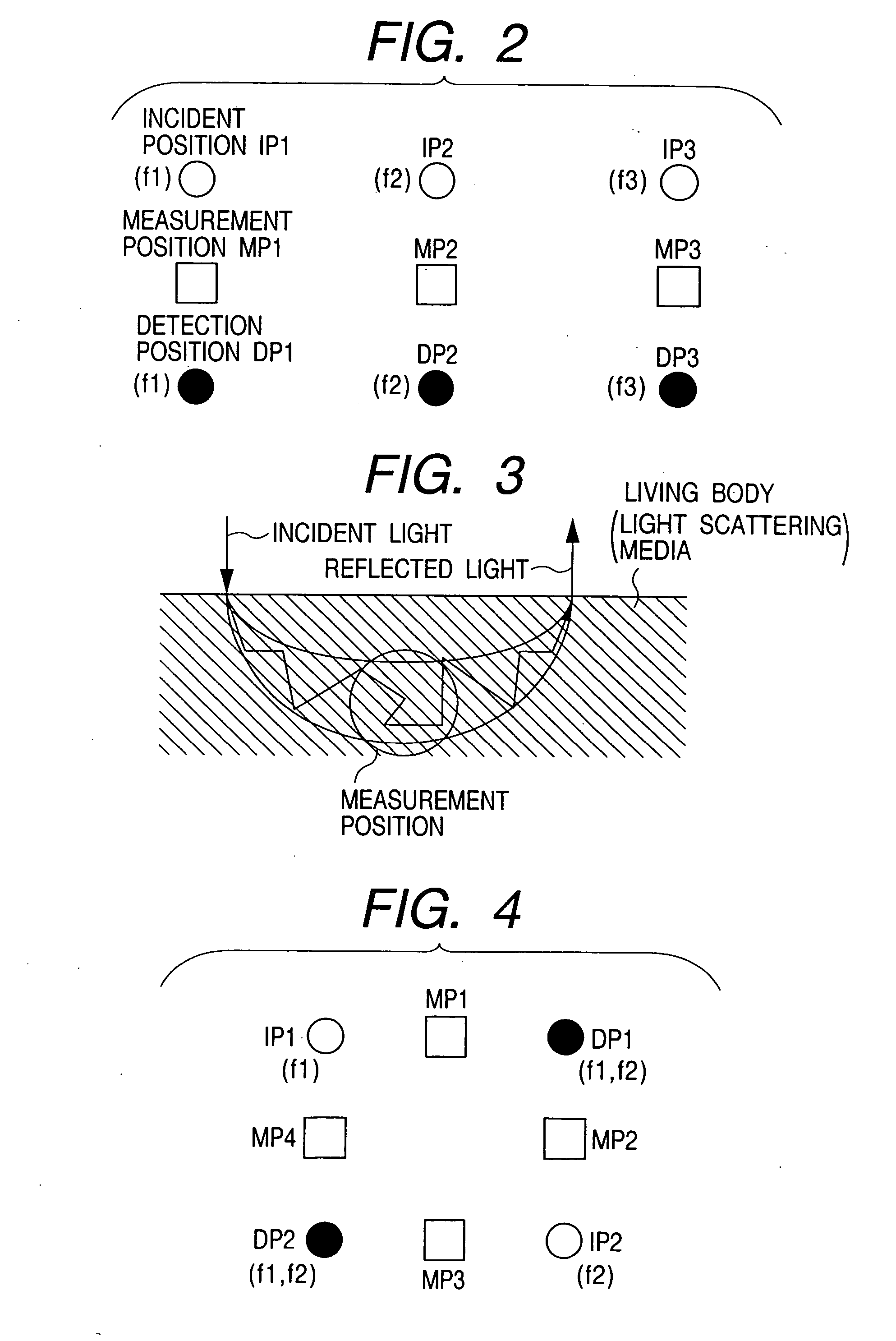
[0111] In the present embodiment, two types of lights (lights of two wavelengths) different in wavelength from each other are used as incident lights with the objective of measuring oxy- and deoxy-hemoglobin concentration changes in a subject (living body). Further, the number of light incident positions and the number of light detection positions are set to two respectively. It is however easy to further increase the number of these incident lights (number of wavelengths), the number of the light incident positions and the number of the light detection positions. It is needless to say that with the increase in the number of the incident lights (number of wavelengths), light-absorption substance concentration changes in other living bodies such as cytochrome, my...


PUM


Abstract

An input instrument for a living body, using an optical measurement system for the living body, includes first and second light incident units arranged on a head of a living body, and first and second light detectors which are paired with the first and the second light incident units respectively, and which are provided to collect light which passes through the living body based on the light irradiated onto the head of the living body by the light incident means. Measurement signals are obtained by measuring a plurality of regions of the living body by the first and the second light incident units, the first and the second light detectors, and characteristic parameters of the signals of an arbitrary time interval of the measured signals are calculated.

Description

CROSS REFERENCE TO RELATED APPLICATION: [0001] This is a continuation of U.S. Ser. No. 10 / 689,760, filed Oct. 22, 2003, which is a continuation of U.S. application Ser. No. 09 / 849,409, filed May 7, 2001, now U.S. Pat. No. 6,640,133, which is a continuation of U.S. application Ser. No. 08 / 875,081, filed Sep. 29, 1997, now U.S. Pat. No. 6,240,309, issued May 29, 2001, which is a 371 of PCT / JP96 / 03365, filed Nov. 15, 1996, and which is a continuation-in-part of co-pending application Ser. No. 539,871, filed Oct. 6, 1995, by some of the inventors herein, now U.S. Pat. No. 5,803,909, the subject matter of which is incorporated by reference herein. [0002] This application relates to ______ and ______, filed concurrently herewith, and which are continuations of Ser. No. 10 / 689,760, filed Oct. 23, 2003.BACKGROUND OF THE INVENTION [0003] 1. Field of the Invention [0004] The present invention relates to an instrument for measuring information on an inner living body with light. [0005] 2. Desc...

Claims


Application Information

Patent Timeline
Patent Type & Authority Applications(United States)
IPC IPC(8): A61B6/00
CPCA61B5/0059A61B5/055A61B5/14552A61B5/14553A61B5/18A61B5/6814A61B6/03
Inventor YAMASHITA, YUICHIMAKI, ATSUSHIKOIZUMI, HIDEAKI
Owner YAMASHITA YUICHI
Learn More