
Image processing apparatus and method

a technology of image processing and apparatus, applied in the field of apparatus and methods, can solve the problems of substantial reduction of referred pictures and inability to maximize coding efficiency, and achieve the effect of increasing coding efficiency

Inactive Publication Date: 2006-08-03
CANON KK
View PDF2 Cites 17 Cited by
  • Summary
  • Abstract
  • Description
  • Claims
  • Application Information

AI Technical Summary

Benefits of technology

[0019] The present invention has been made to solve the conventional problems, and has as its object to provide a coding method and apparatus capable of increasing the coding efficiency.

Problems solved by technology

The number of substantially referred pictures decreases in the reference list, and the coding efficiency cannot be maximized.

Method used


Image

  • Image processing apparatus and method
  • Image processing apparatus and method
  • Image processing apparatus and method

Examples


first embodiment

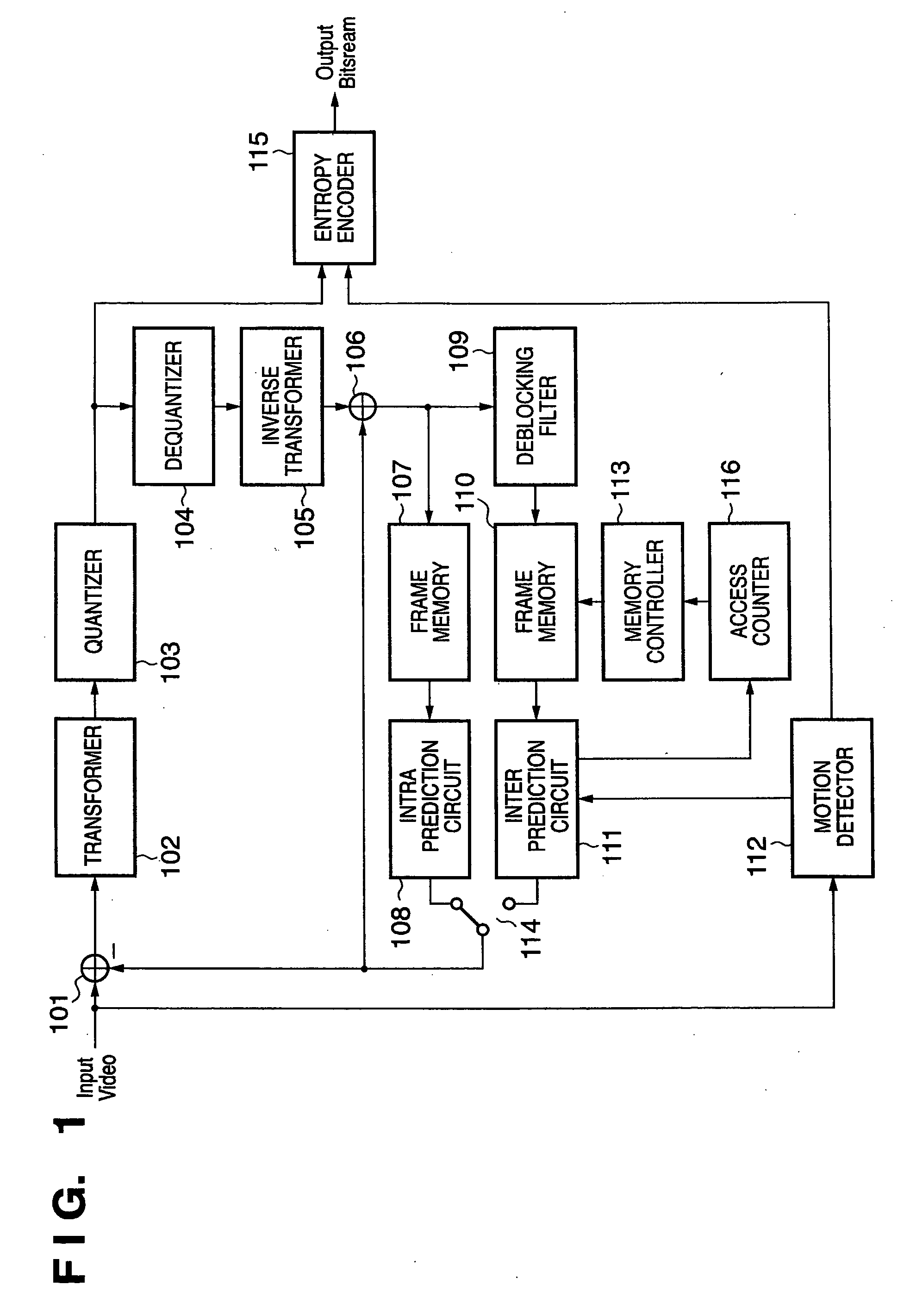
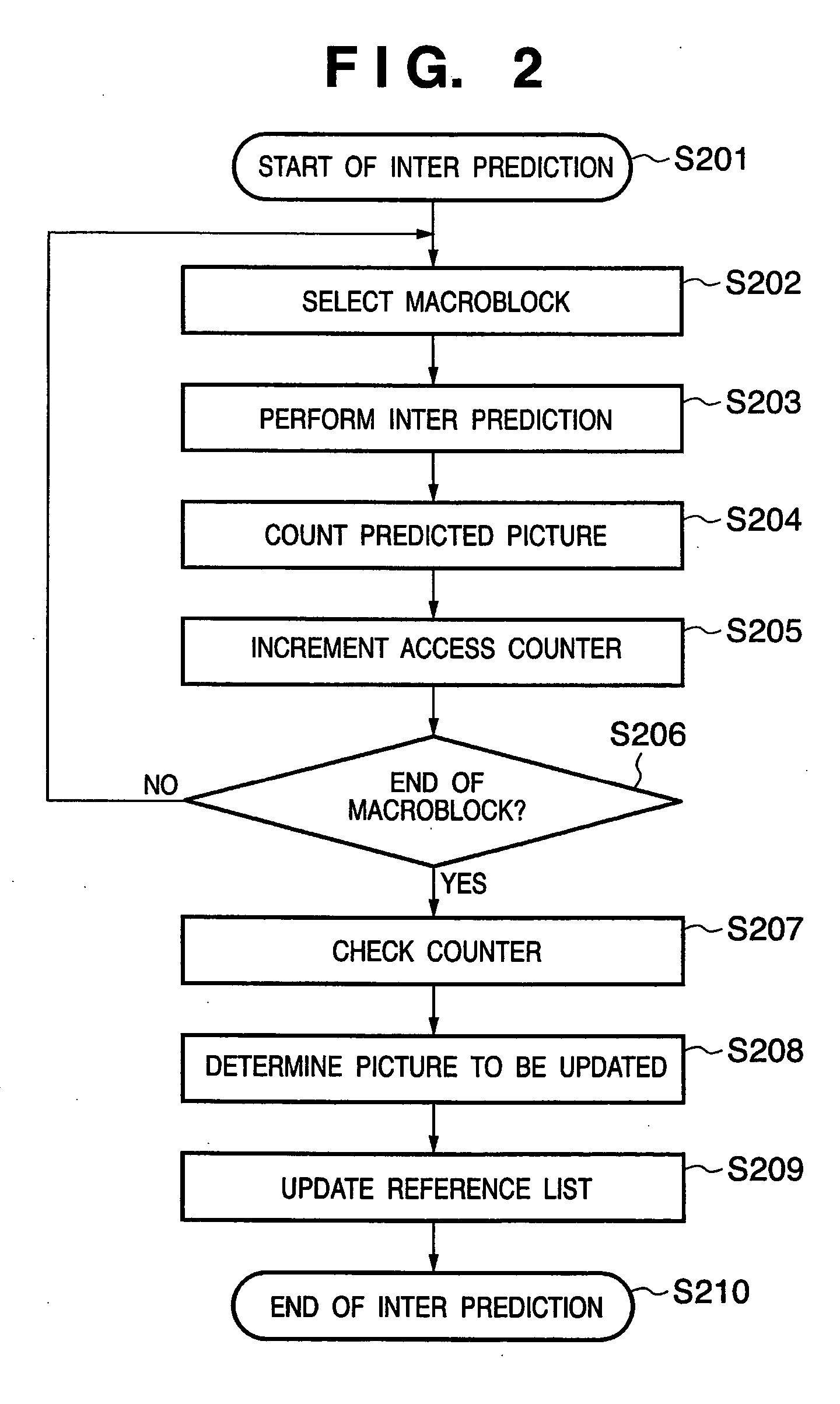
[0036] A compression procedure according to the present invention will be explained with reference to FIGS. 1 to 4. FIG. 1 is a block diagram showing a compression coding apparatus according to the first embodiment. Image data is compression-encoded on the basis of H.264.

[0037] In FIG. 1, image data is divided into macroblocks and then input, and a difference from a predicted value is obtained by a subtracter 101. The difference image undergoes integer DCT transform by a transformer 102 to acquire an integer DCT transform coefficient. The integer DCT transform coefficient is quantized by a quantizer 103. The quantized data is sent as difference image data to an entropy encoder 115. At the same time, the quantized data is also supplied to a dequantizer 104 and dequantized to acquire an integer DCT coefficient again. The coefficient undergoes inverse integer DCT transform by an inverse transformer 105 to obtain the above-mentioned difference image. A predicted value is added to the d...

second embodiment

[0058] The second embodiment will be explained with reference to FIGS. 5 and 6. The configuration of a compression coding apparatus according to the second embodiment is the same as that according to the first embodiment, and a detailed description thereof will be omitted.

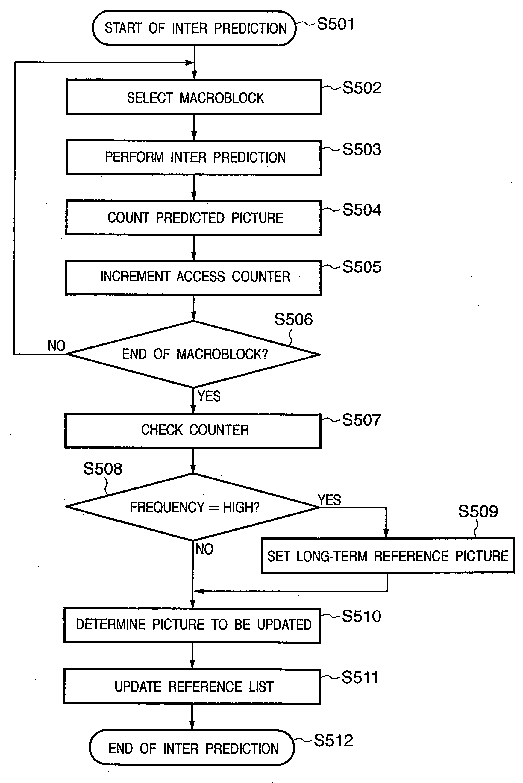
[0059] The second embodiment is different from the first embodiment in that, when the reference list is to be updated, the count at which each reference picture is used for prediction is measured by an access counter, and a reference picture of especially a high access count is changed to a long-term reference picture.

[0060] Processing according to the second embodiment will be explained with reference to the flowchart of FIG. 5.

[0061] In step S502 of FIG. 5, the first macroblock subjected to inter prediction is selected. In step S503, motion detection is done for reference pictures to execute inter prediction.

[0062] In step S504, which of pictures is referred to is determined as a result of inter prediction. I...


PUM


Abstract

This invention provides a coding method and apparatus capable of increasing the coding efficiency. According to this invention, an image processing apparatus which performs predictive coding using image data of a different frame as a reference picture includes a prediction unit which performs motion compensated prediction for each reference picture in at least one reference list formed from a set of reference pictures for prediction, a reference list update unit which updates the reference list by adding or deleting the reference picture, a reference counter unit which measures, for each reference picture, a count at which the reference picture is used for motion compensation predictive coding, and an update picture determination unit which determines a reference picture to be updated in the reference list by using the measurement result of the reference counter unit.

Description

FIELD OF THE INVENTION [0001] The present invention relates to an apparatus and method which compress and record image data and, more particularly, to an apparatus and method which compress image data using MPEG-4 part-10: AVC (ISO / IEC 14496-10, also called H.264). BACKGROUND OF THE INVENTION [0002] Various methods of compressing and recording image data have conventionally been proposed. There is newly proposed MPEG-4 part-10: AVC (ISO / IEC 14496-10, also called H.264) (to be referred to as H.264 hereinafter). [0003] An H.264 compression procedure will be explained with reference to FIG. 7. In FIG. 7, input image data is divided into macroblocks. A difference from a predicted value is obtained by a subtracter 701, undergoes integer DCT transform by a transformer 702, and is quantized by a quantizer 703. The quantized data is sent as difference image data to an entropy encoder 715. [0004] At the same time, the quantized data is dequantized by a dequantizer 704, and undergoes inverse ...

Claims


Application Information

Patent Timeline
IPC IPC(8): H04N5/91H04N19/50H04N19/102H04N19/136H04N19/176H04N19/196H04N19/423H04N19/503H04N19/51H04N19/577H04N19/61H04N19/625H04N19/91
CPCH04N9/8045H04N9/8047H04N19/105H04N19/58H04N19/61H04N19/573H04N19/176
Inventor MAKINO, JUN
Owner CANON KK
Learn More