
Method for maintaining register integrity and receive packet protection during ULPI PHY to LINK bus transactions

Inactive Publication Date: 2006-07-27
MICROCHIP TECH INC
View PDF7 Cites 3 Cited by
  • Summary
  • Abstract
  • Description
  • Claims
  • Application Information

AI Technical Summary

Benefits of technology

[0029] Various embodiments of the system and method suggested by the present invention may allow a more robust development and debugging of USB physical layers (PHYs), by allowing users to find USB receive packets that may have been dropped by the USB PHY. Protecting register write operations according to various embodiments of the present invention may allow the USB LINK to see the packets but still abort one cycle later in the receive process.
[0030] Thus, various embodiments of the systems and methods described above may facilitate design of a system that protects register write operations, especially register write operations within USB PHY, which may be protected such that a disconnect or another unexpected state may not appear at the other end of the USB, thus preventing the other end of the USB bus to possibly go into Host Negotiation Protocol (HNP), or simply disconnect or suspend. Preferred embodiments, as described herein, may also protect against noise causing a write to a register within the USB PHY.

Problems solved by technology

Concurrently, the introduction of smaller deep sub-micron processes present new challenges, such as integrating the physical layer (PHYtransceiver) analog circuitry required by technologies such as USB and OTG, leading to increased man-hours, fiscal and time investment, and silicon revisions.
Pre-existing specifications, including UTMI and UTMI+ were developed primarily for Macrocell development, and were thus not optimized for use as an external PHY.
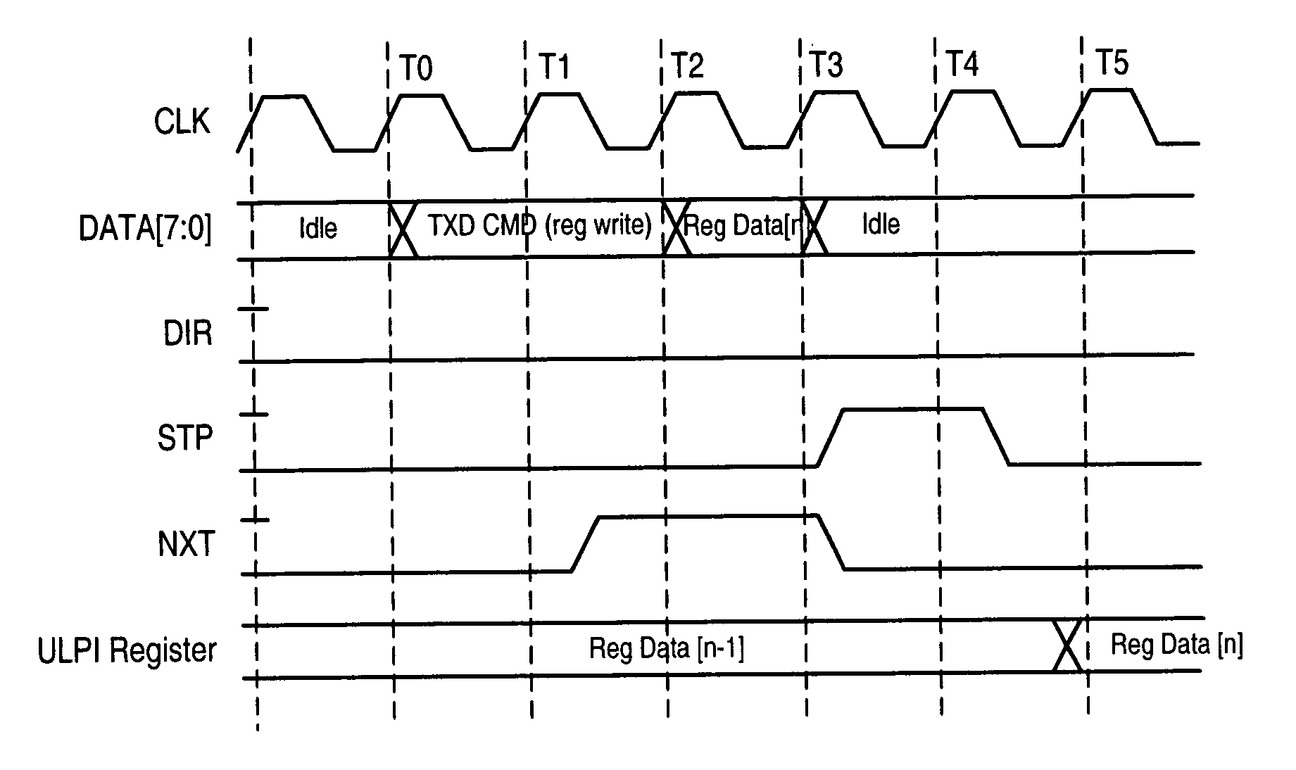
However, in the link re-scheduling a write, the correct data may not necessarily be written during the next write operation.
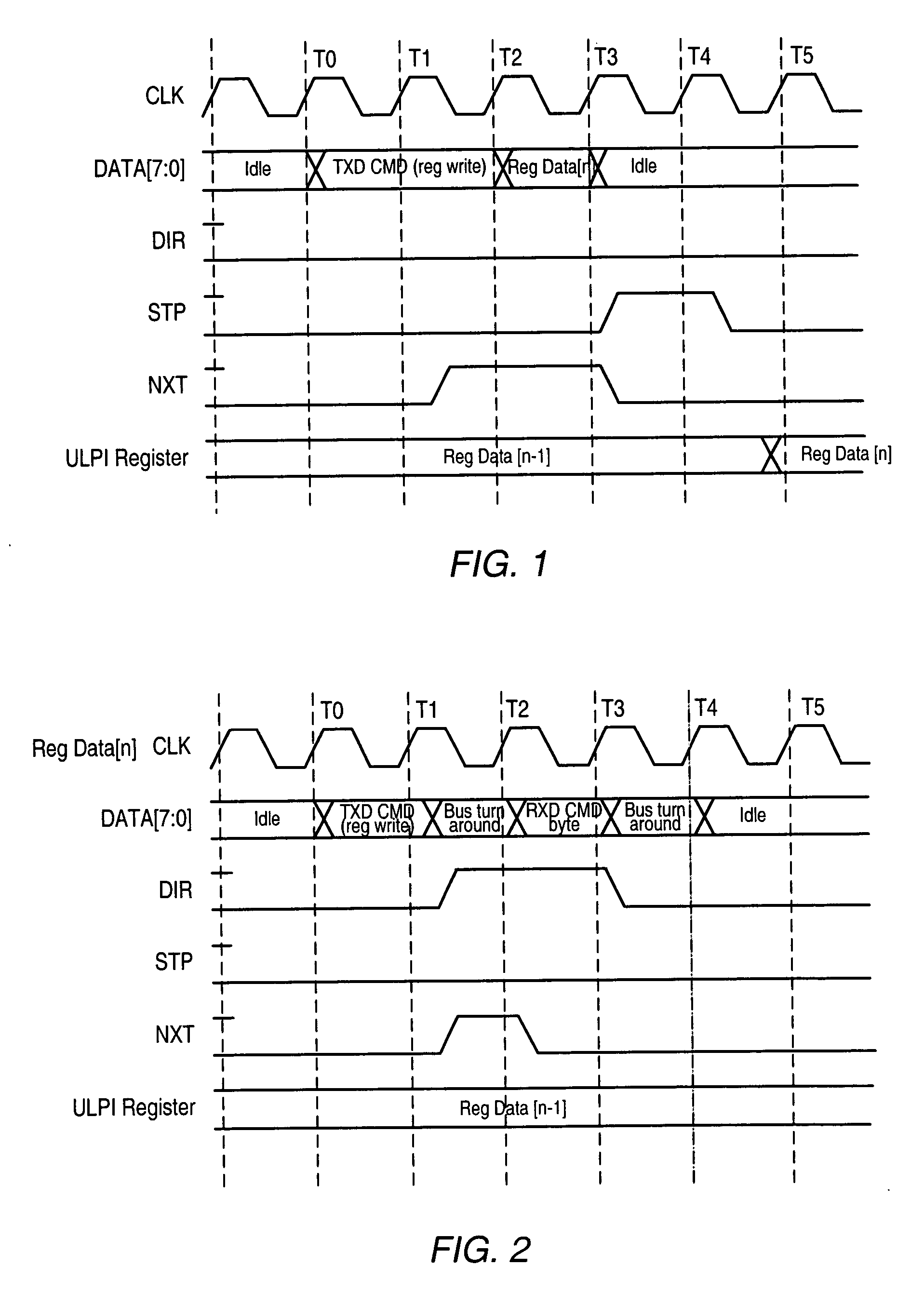
In the USB protocol, unanticipated changes on DP / DM—caused by a write to the Function control register, for instance—may be misinterpreted on the other end of the USB bus leading to an unexpected state, which would interfere with proper operation of the USB devices on either end of the USB bus.
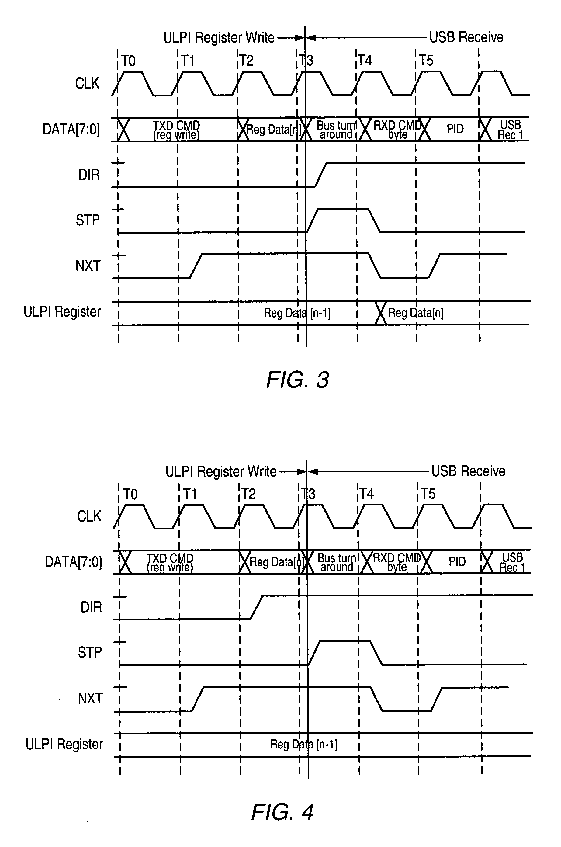
As a result of this action by the link, the incoming USB received packet may be lost and the link may be unaware that it has just aborted the PHY's USB receive.
In practice this may lead to unexpected register writes when in development.
However, requiring the link to sample the DIR signal would preclude the design of a clean synchronous interface to the PHY.
This may result in a situation where an interrupt causes the ULPI PHY to report a status change via the RXD command byte to the LINK, or a USB receive occurs, causing USB data to be transferred to the LINK.
Any of the above conditions may occur at any time and may interrupt a register write operation already in progress.

Method used


Image

  • Method for maintaining register integrity and receive packet protection during ULPI PHY to LINK bus transactions
  • Method for maintaining register integrity and receive packet protection during ULPI PHY to LINK bus transactions
  • Method for maintaining register integrity and receive packet protection during ULPI PHY to LINK bus transactions

Examples


Embodiment Construction

[0039] As used herein, a “trigger” signal is defined as a signal that is used to initiate, or “trigger”, an event or a sequence of events in a digital system. A trigger signal is said to be in a “triggering state” at a time when it initiates a desired event, or sequence of events. A periodic trigger signal may commonly be referred to as a “clock”. In a “synchronous” digital system, generally a clock, commonly referred to as a “system clock”, may be used for initiating most events, or sequences of events. An example of a triggering state may be, but is not limited to, a rising edge of a pulse of a clock in a synchronous digital system. “Asserting” a signal refers to setting a level of the signal to a high logic level, whereas “deasserting” a signal refers to setting an output of the signal to a low logic level. It will be evident to those skilled in the art that a high logic level may be physically represented by either a high voltage or a low voltage, and similarly a low logic level...


PUM


Abstract

A system and method for protecting register write operations, especially register write operations performed in a USB PHY. A USB transmitter / receiver, operable to receive a register write command from a USB LINK device, may monitor the write sequence initiated by the register write command to determine if / when the register write sequence has been interrupted. In monitoring the register write sequence, the USB transmitter / receiver is operable to discard the register write command if a DIR signal issued by the USB transmitter / receiver is asserted during the register write sequence and / or if an STP signal received by the USB transmitter / receiver is asserted during the register write sequence, where STP may be part of a normal register write operation. The USB transmitter / receiver is further operable to allow the register write sequence to complete if the STP signal and the DIR signal are not asserted during a predetermined period of the register write sequence. The monitoring functions may be implemented in a finite state machine comprised in the USB transmitter / receiver.

Description

BACKGROUND OF THE INVENTION [0001] 1. Field of the Invention [0002] This invention relates to digital interface design, and more particularly, to designing a ULPI (UTMI+ Low Pin Interface). [0003] 2. Description of the Related Art [0004] Within the past two decades personal computers (PC) have joined television sets, high fidelity stereo equipment, and compact disc players as part of the vast array of electronic devices widely used in both the office and the home. The Universal Serial Bus (USB) was developed to offer PC users an enhanced and easy-to-use interface for connecting an incredibly diverse range of peripherals to their computers. The development of the USB was initially driven by considerations for laptop computers, which greatly benefit from a small profile peripheral connector. Among the many benefits of the USB is a reduction in the proliferation of cables that can affect even the smallest computer installations. In general, USB has become the interface of choice for PC...

Claims


Application Information

Patent Timeline
IPC IPC(8): G06F3/00
CPCG06F13/4286
Inventor MONKS, MORGANYUP, BING
Owner MICROCHIP TECH INC
Learn More