
Follicular transplantation device and method

a transplantation device and follicular technology, applied in the field of hair transplantation devices, can solve the problems of large linear scars left by the removal of the donor scalp in the donor area, many potential donor areas are undesirable, and the hair follicle harvesting tools are not suitable for use, so as to achieve accurate location and removal

Inactive Publication Date: 2006-07-20
KACHENMEISTER ROBERT M
View PDF22 Cites 69 Cited by
  • Summary
  • Abstract
  • Description
  • Claims
  • Application Information

AI Technical Summary

Benefits of technology

[0007] An aspect of at least one of the embodiments disclosed herein includes the realization that the shaft of a hair of an animal can be used as a guide for removing individual hairs for implantation elsewhere. For example, tubular members can be used in a manner that the tubular member is slid over a hair shaft in a manner that the tubular member is guided, by the hair shaft, to the follicle. As such, the follicle itself can be more accurately located and removed for implantation elsewhere.
[0008] In one embodiment of the present invention, a hair removal device is disclosed. The hair removal device comprises a guiding inner tubular member with a blunt distal end and an outer tubular member. Both the inner tubular member and the outer tubular member have distal ends configured to expand a pore around the hair follicle. Once the hair follicle is removed, the pore will quickly return to its normal size. By expanding the pore surrounding the hair follicle rather than cutting tissue, the risk of scarring with the hair removal device is significantly reduced over the conventional techniques. This inner tubular member is configured such that it can be slid over a hair in the donor area and into the dermal tissue into which the hair is rooted. The blunt distal end of the inner tubular member can be advanced until the inner tubular member contacts the upper service of the hair follicle bulb. Therefore the inner tubular member is able to locate the hair follicle bulb using the hair shaft itself as a guide. The outer tubular member is configured to be slidably engaged over the inner tubular member over the hair to be removed. The outer tubular member comprises an inner dilating portion and an outer harvesting portion. At the distal end of the outer tubular member, the inner dilating portion has a honed dilating blade tip, while the outer harvesting portion has a honed tip. Once the outer tubular member is slidably advanced over the inner tubular member to a position in the dermal tissue adjacent the upper surface of the hair follicle bulb, the harvesting portion of the outer tubular member can be advanced around the hair follicle bulb. The harvesting portion is configured so that it will dilate the pore surrounding the hair follicle bulb and cut dermal tissue surrounding the hair follicle bulb, thereby leaving the hair follicle bulb free to be extracted. Once the pore surrounding the hair follicle bulb has been dilated and dermal tissue around the hair follicle bulb has been cut, the outer tubular member can then be retracted along with the hair follicle bulb.
[0011] Another embodiment of the present invention is a hair removal method using a hair removal device as described above. The hair removal method generally comprises the steps of sliding an inner tubular member over a hair in a donor area. As noted above, the inner tubular member can be advanced until it reaches an upper surface of the hair follicle bulb. Preferably, the inner tubular member will be configured to ease this positioning by having an inner diameter that allows the inner tubular member to fit around the hair shaft but is not large enough to allow it to fit around the hair follicle. This configuration allows the inner tubular member to use the hair shaft as a guide to locate the hair follicle bulb under the visible surface layer of skin. Once the inner tubular member reaches the upper surface of the hair follicle, the method further comprises sliding an outer tubular member over the inner tubular member. The outer tubular member can be configured with an inner dilating portion and an outer harvesting portion configured such that the outer harvesting portion can be slidably advanced or retracted relative to the inner dilating portion. This configuration allows the outer tubular member to dilate the dermal tissue surrounding the hair and hair follicle using a dilating distal end of the inner dilating portion, then dilate the pore surrounding the hair follicle bulb and cut the dermal tissue surrounding the hair follicle by further advancing the outer harvesting portion around the follicle. Finally, the method comprises withdrawing the outer tubular member with a hair follicle. In another aspect of the hair removal method, the step of withdrawing the outer tubular member with a hair follicle can be accomplished with the aid of a suction device.

Problems solved by technology

One significant drawback with the traditional hair transplant method is that the removal of donor scalp leaves large linear scars in the donor area.
Because of the undesirability of the scars left by the conventional method, many potential donor areas are undesirable as most people would prefer not to have visible scaring across their arms, legs, or other potential donor areas.
However, such the hair follicle harvesting tools have other drawbacks.
Moreover, due in part to the precision required and in part to an offset between the visible hair root on the scalp and the hair follicle bulb under the scalp, these tools frequently transect, injure, or destroy hair follicle bulbs in removal attempts.

Method used


Image

  • Follicular transplantation device and method
  • Follicular transplantation device and method
  • Follicular transplantation device and method

Examples


Embodiment Construction

[0041] Turning now to the drawings provided herein, a more detailed description of the embodiments of the present inventions is provided below. It should be noted, however, that while some embodiments have all of the advantages identified herein, other embodiments may only realize some but not all of the advantages.

[0042] Hair Transplantation Device

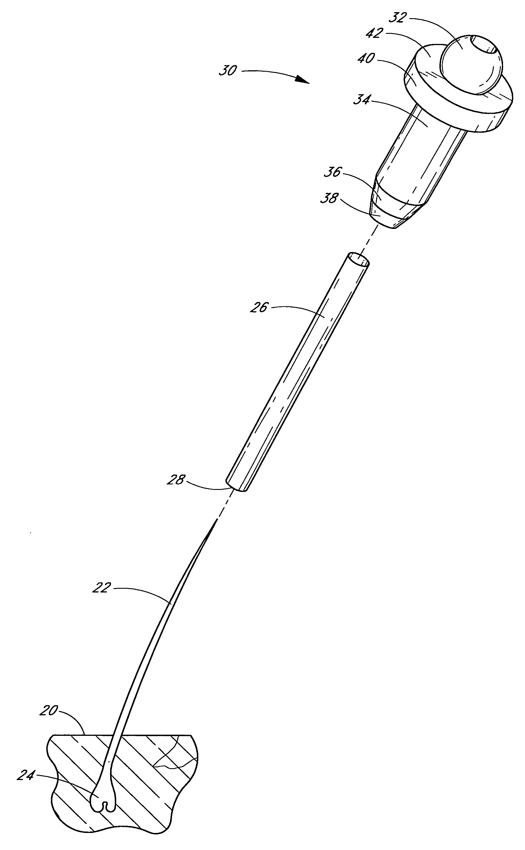
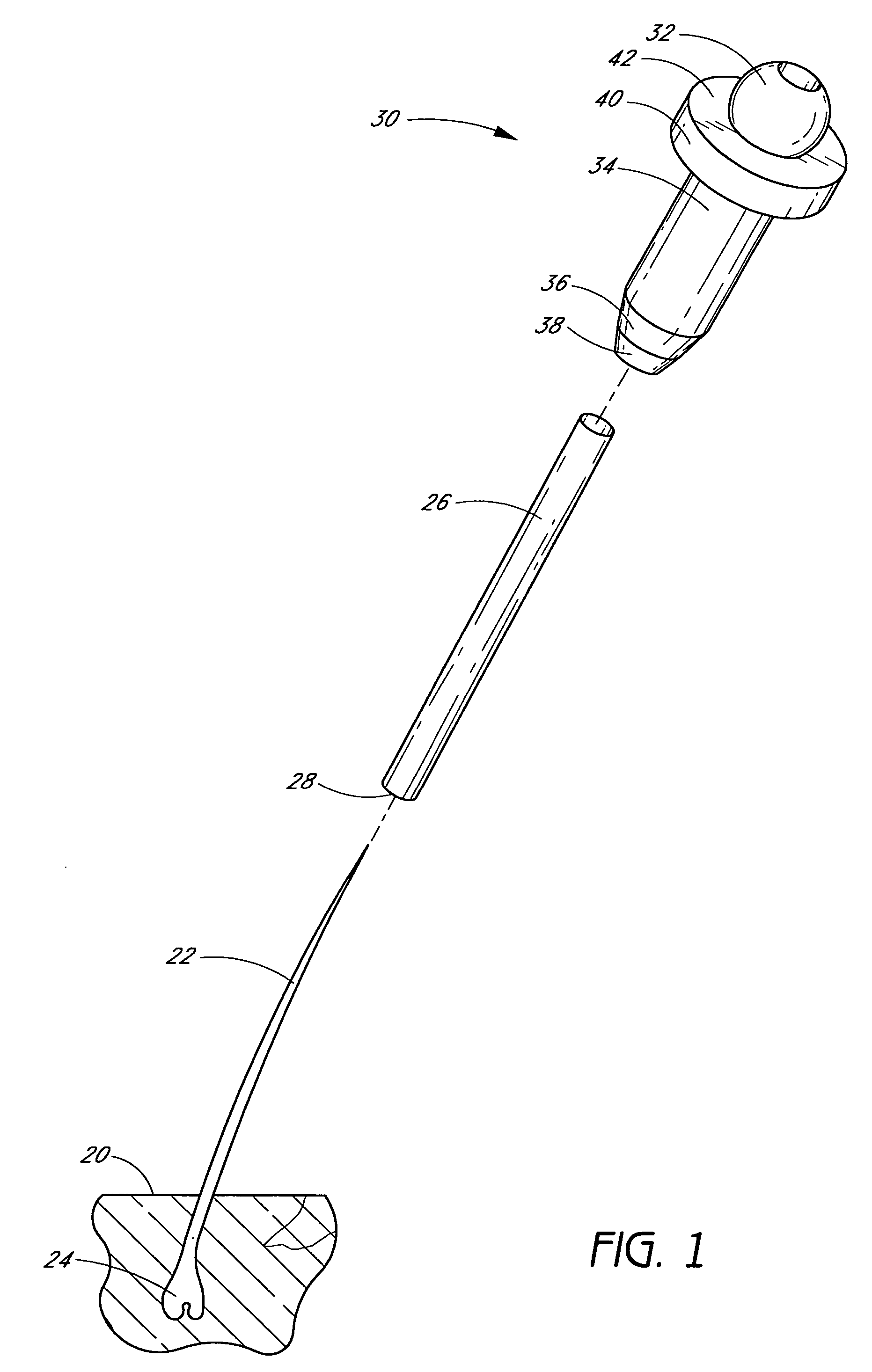
[0043] With reference to FIGS. 1-6, various embodiments of a hair transplantation device are depicted. FIG. 1 depicts an exploded perspective view of a hair transplantation device. The hair transplantation device comprises an inner tubular member 26 and an outer tubular member 30.

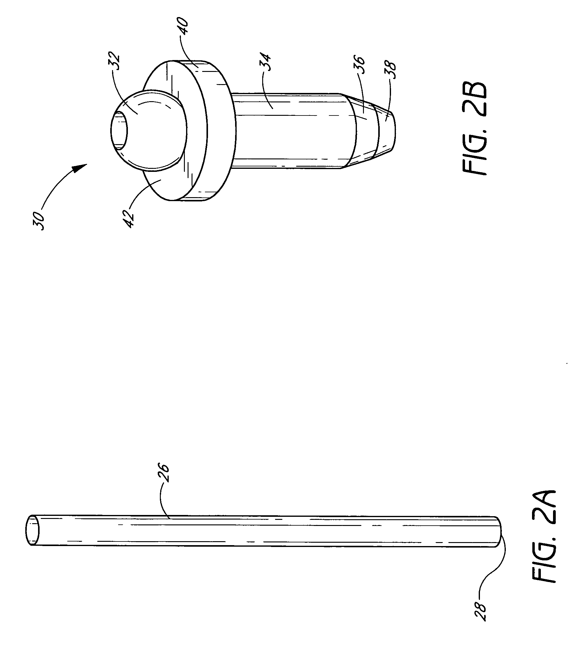
[0044] The inner tubular member 26 of the hair transplantation device of FIG. 1 is depicted in FIG. 2A. The inner tubular member 26 can have a generally tubular shape allowing it to be slidably advanced over a shaft of hair to provide a guide to the hair follicle bulb. In some embodiments, the inner diameter can be about the same or slightly larger than an ave...


PUM


Abstract

A hair transplantation device can include a generally tubular guide configured to locate a hair follicle bulb by sliding over a hair shaft down to an upper surface of a hair follicle. The guide can have a blunt distal end configured not to transect the hair follicle bulb. The hair transplantation device also includes an outer tubular member sized and configured to be advanced around the guide. The outer tubular member has a dilator and a harvester. The device can be used in a follicle transplantation method in which the guide locates a hair follicle bulb, and the outer tubular member is slid over the guide. Once the outer tubular member is aligned with the guide, the harvesting portion is advanced, cutting dermal tissue surrounding the hair follicle. The outer tubular member is then withdrawn with the hair follicle, relocated in a recipient area, and the hair follicle implanted.

Description

RELATED APPLICATION DATA [0001] This application claims priority to U.S. Provisional Application No. 60 / 639,120 entitled “FOLLICULAR TRANSPLANTATION DEVICE AND METHOD” filed on Dec. 23, 2004, the entire contents of which is hereby incorporated by reference.BACKGROUND OF THE INVENTIONS [0002] 1. Field of the Inventions [0003] The present inventions relate to hair transplant devices and, in particular, to devices for harvesting hair follicles from animal dermis and devices for implanting the hair follicles into animal dermis. [0004] 2. Description of the Related Art [0005] Hair transplant procedures have been carried out for decades. Conventional hair transplant operations are performed with the following process: harvesting of a piece of scalp in the donor area to obtain a transplanting skin (so called “donor scalp”), pulling and suturing the remaining portion of donor area skin after harvest from the donor area, separating each of the hairs including the hair follicle roots from the...

Claims


Application Information

Patent Timeline
IPC IPC(8): A61B17/50
CPCA61B17/32053A61B17/3468A61B2017/00752A61B2017/00969A61B2019/303A61B2217/005A61F2/10A61B2090/033
Inventor KACHENMEISTER, ROBERT M.
Owner KACHENMEISTER ROBERT M
Learn More