
Short-range wireless communication apparatus and cellular phone terminal

a wireless communication and short-range technology, applied in the direction of transmission monitoring, drying solid materials, drying machines, etc., can solve the problems of user inability to see the mark, crowded checkout counter, user congestion around automatic gate,

Inactive Publication Date: 2006-07-20
SONY CORP
View PDF30 Cites 61 Cited by
  • Summary
  • Abstract
  • Description
  • Claims
  • Application Information

AI Technical Summary

Benefits of technology

[0031] That is, according to embodiments of the invention, it is possible to detect the magnetic field strength of a carrier wave used for short-range wireless communication, the signal communication by short-range wireless communication, and whether or not the function of short-range wireless communication is locked into the disabled state and then notify the user of them.
[0032] According to embodiments of the invention, since it is possible to detect the magnetic field strength of a carrier wave and notify the user of it while notifying the user of the communication state of short-range wireless communication, for example it is possible to surely and immediately notify the user of the distance between the contactless IC card reader / writer and the contactless IC card within which the contactless IC card reader / writer and the contactless IC card can communicate well with each other, not through the MPU of the contactless IC card or the CPU of the cellular phone terminal. Further, since it is also possible to detect whether or not the function of short-range wireless communication is locked into the disabled state, for example if the contactless IC card function is locked into the disabled state, it is possible to surely notify the user as such.

Problems solved by technology

As a result, the following problems arise.
In the case where the RFID system is in the no response state, at first the user cannot grasp what has happened, and it takes time to recognize that a communication error has occurred between the RFID card reader / writer and the RFID card.
Therefore, in a case where the RFID system is used for an automatic gate in a station, a communication error takes the user some time to pass through the automatic gate, thereby causing congestion in the flow of users around the automatic gate.
Further, in a case where the RFID system is used for a checkout counter in a store, a communication error prevents the user from smoothly paying for a purchase at the checkout counter in the store, thereby causing crowdedness around the checkout counter.
However, at the time of actually holding the cellular phone terminal over the RFID card reader / writer, it is necessary to place the specified mark face to the RFID card reader / writer; therefore, the user cannot see the mark.
Thus, in the past RFID system, a problem such as a communication error caused by positional deviation between the RFID card reader / writer and the RFID card is more likely to occur.
Furthermore, in the past RFID system, the user cannot know the distance between the RFID card reader / writer and the cellular phone terminal (RFID card) within which the RFID card reader / writer and the cellular phone terminal can communicate well with each other.
In other words, the user cannot know the distance between the RFID card reader / writer and the cellular phone terminal beyond which the RFID card reader / writer and the cellular phone terminal cannot communicate with each other.
Accordingly, the user feels inconvenient and uneasy about using the RFID card.

Method used


Image

  • Short-range wireless communication apparatus and cellular phone terminal
  • Short-range wireless communication apparatus and cellular phone terminal
  • Short-range wireless communication apparatus and cellular phone terminal

Examples


Embodiment Construction

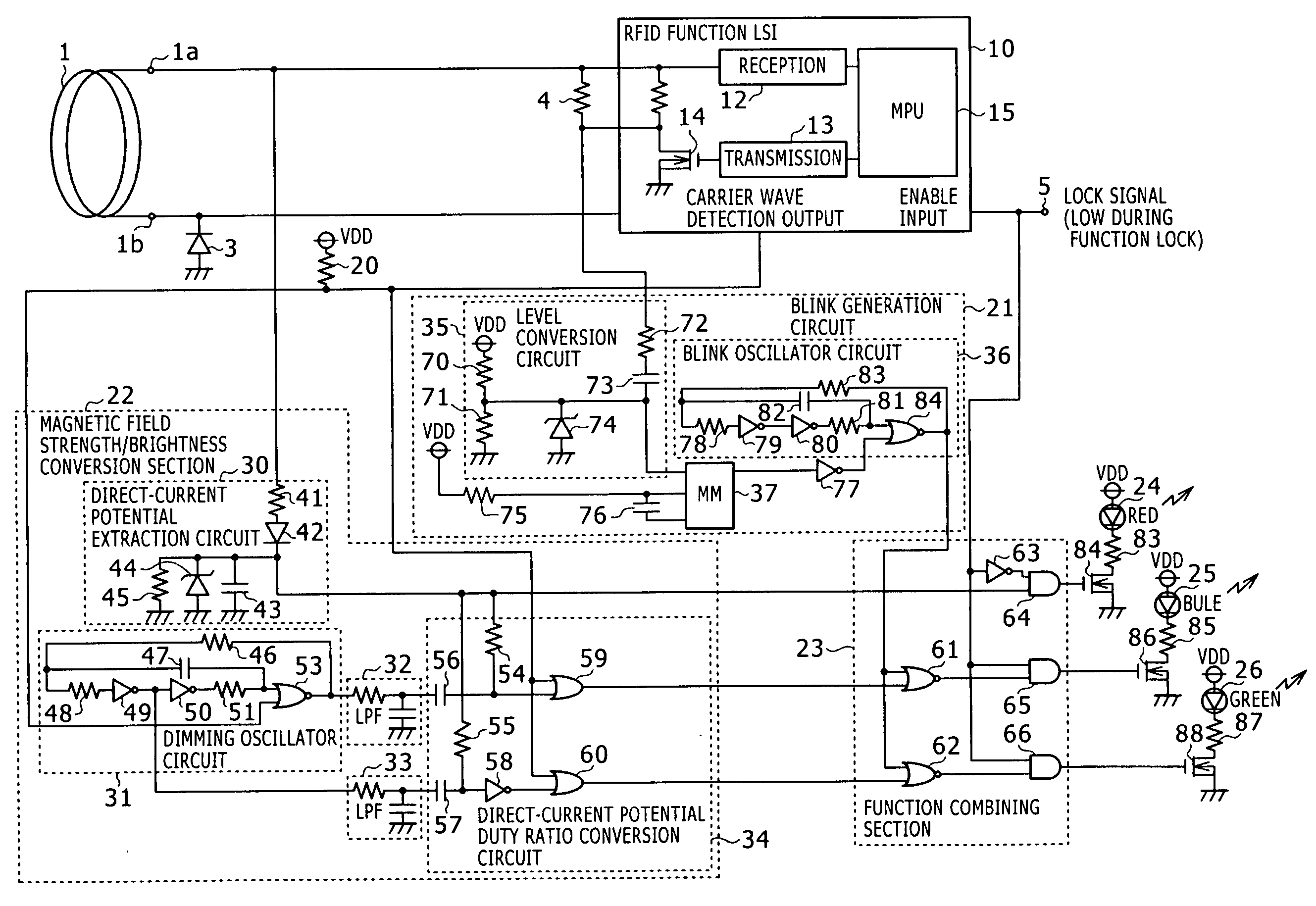
[0038] Hereinafter, an embodiment of the present invention will be described with reference to the accompanying drawings.

[0039] In the following description, a cellular phone terminal having a built-in RFID card is exemplified as an embodiment of a short-range wireless communication apparatus and a cellular phone terminal according to an embodiment of the invention. However, the description in this specification is just an example, and it is needless to say that the invention is not limited to this example.

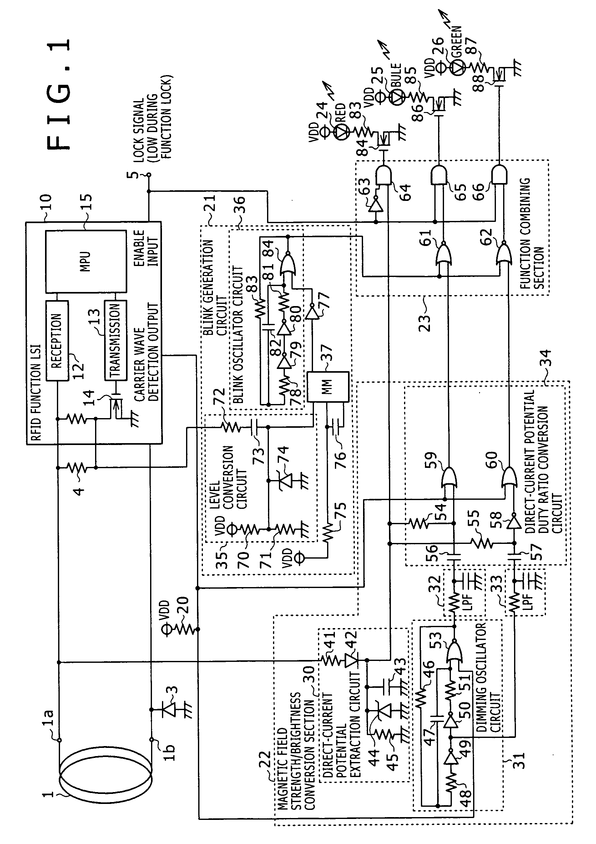
[0040] [Outline of internal circuit configuration]FIG. 1 is a schematic circuit diagram of a short-range wireless communication apparatus according to this embodiment of the invention in which a circuit configuration according to this embodiment is provided at a transponder section of a general RFID card.

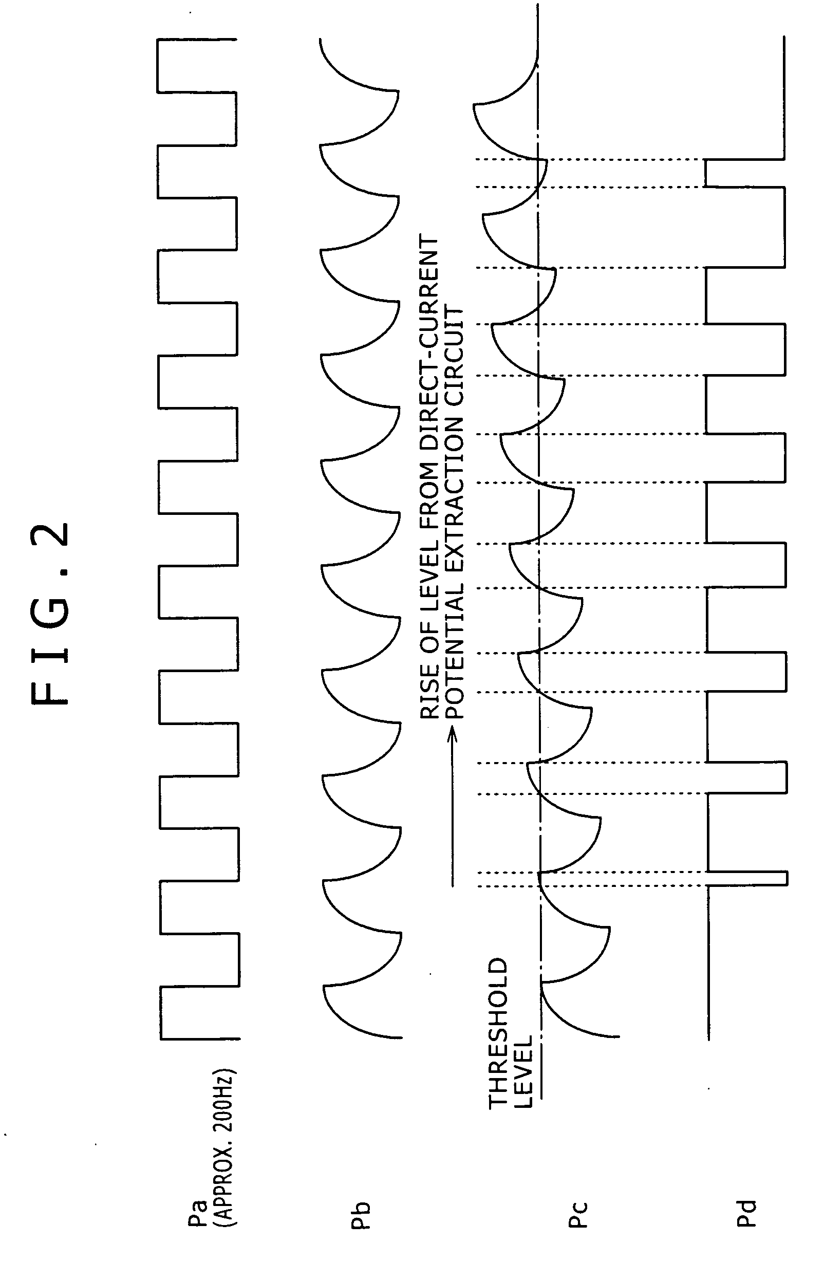
[0041] The short-range wireless communication apparatus according to this embodiment has a first lighting control function for lighting e.g. a blue light upon detection of a ca...


PUM


Abstract

There is provided a short-range wireless communication apparatus and a cellular phone terminal that can surely and immediately notify a user of the optimum distance between a contactless IC card reader / writer and a contactless IC card not through an MPU or a CPU and if the contactless IC card function is locked, surely notify the user as such. In an RFID card, a magnetic field strength / brightness conversion section adjusts the brightness of two LEDs in accordance with the detected magnetic field strength of a carrier wave. A blink generation circuit detects whether the RFID card is in a communication state and blinks the LEDs if so. A function combining section combines the functions to indicate the magnetic field strength and the communication state with the brightness and blinking of the LEDs. An LED with another color illuminates only when an RFID function LSI is in a lock state.

Description

CROSS REFERENCES TO RELATED APPLICATIONS [0001] The present invention contains subject matter related to Japanese Patent Application No. 2005-009462 filed in the Japanese Patent Office on Jan. 17, 2005, the entire contents of which being incorporated herein by reference. BACKGROUND OF THE INVENTION [0002] 1. Field of the Invention [0003] The present invention relates to a short-range wireless communication apparatus which performs information communication with, e.g., a so-called contactless IC card reader / writer and to a cellular phone terminal having the short-range wireless communication apparatus. [0004] 2. Description of the Related Art [0005] In recent years, a contactless IC card (hereinafter referred to as an RFID card) having a built-in RFID (Radio Frequency-Identification) circuit has been coming into wide use as, e.g. a train ticket and a prepaid card because the RFID card has the advantages of good usability, excellent durability, simultaneous accessibility to multiple c...

Claims


Application Information

Patent Timeline
IPC IPC(8): H04B7/00H04M1/00
CPCG06K19/0707G06K19/0712G06K19/0723H04B17/318H04B5/0056H04B5/0062H04M1/7253G06K19/07703Y02D30/70H04M1/72412H04B5/77A23B7/02A23B4/031A01F25/12F26B3/04F26B21/02
Inventor SUEOKA, TAKASHITSUSHIMA, TAKAAKICHIBA, MASAYUKI
Owner SONY CORP
Learn More