Linear displacement measuring apparatus
a technology of linear displacement and measuring apparatus, applied in the direction of measuring device, instruments, using mechanical means, etc., can solve problems such as inability to obtain correct results
- Summary
- Abstract
- Description
- Claims
- Application Information
AI Technical Summary
Benefits of technology
Problems solved by technology
Method used
Image
Examples
first exemplary embodiment
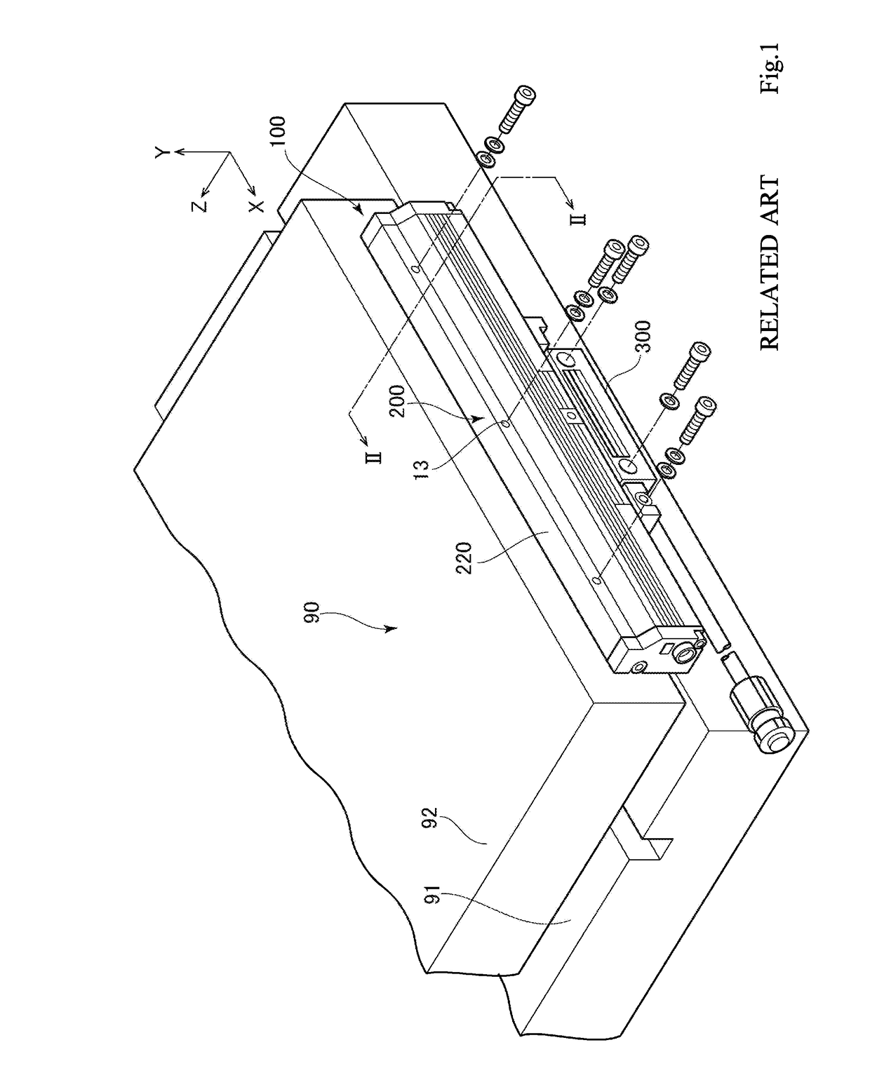
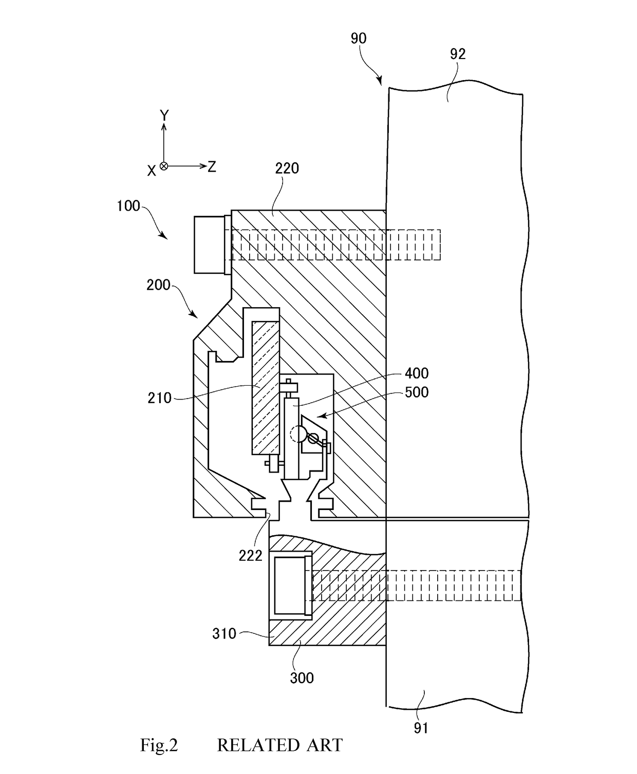
[0052]A feature of the present exemplary embodiment is mainly a structure of a slider 300, and the description of a scale part 200 is omitted since the scale part 200 is similar to the related art.
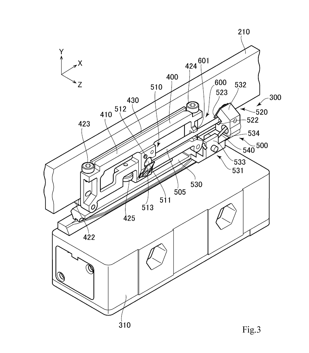
[0053]FIGS. 3 and 4 are perspective views of the slider 300.
[0054]FIG. 5 is a rear face side view of the slider 300.
[0055]The slider 300 includes a traveling body 400, a carriage part 310, coupling means 500, and misalignment detecting means 600. The traveling body 400 travels along a main scale 210 on the main scale 210. The carriage part 310 is provided outside a scale housing case 220 and slides along the scale part 200. The coupling means 500 couples the traveling body 400 with the carriage part 310. The misalignment detecting means 600 detects an installation shift which exceeds a prescribed amount.
[0056]FIG. 6 is a perspective view of a part of the traveling body 400 and the coupling means 500 after the carriage part 310 is removed from the slider 300.
[0057]The traveling body 400 inc...
second exemplary embodiment
[0089]Next, a second exemplary embodiment of the present invention is described below.
[0090]The basic structure of the second exemplary embodiment is similar to that of the first exemplary embodiment, but a feature of the second exemplary embodiment is to add a pressing plate 603 as misalignment detecting means 600 (see FIG. 11). In the above described first exemplary embodiment, the connecting rod 505 is received between the two projecting pieces 601 separated from each other in the Y-axis direction. Thus, when the main scale 210 is inclined in the Y-axis direction, the inclination is able to be detected. However, when the main scale 210 is shifted in, for example, the Z-axis direction, the shift cannot be detected in the first exemplary embodiment.
[0091]For example, in FIG. 10, an encoder (a linear displacement measuring apparatus 100) detects the position of a gate type slider 93 which moves forward and backward in the X-axis direction.
[0092]At this time, although a scale part 20...
third exemplary embodiment
[0098]In a second exemplary embodiment, the pressing plate 603 is fixed on the base frame part 410. As means for regulating relative displacement between a connecting rod 505 and a traveling body 400 in the Z direction, for example, a pressing plate 604 may be provided at the tip of a projecting piece 601 as illustrated in FIG. 12. The pressing plate 604 is provided so as to be bent from the tip of the projecting piece 601 to have an L shape overhanging the connecting rod 505. With the pressing plate 604, an effect similar to the second exemplary embodiment is obtained.
PUM
 Abstract
Description
Claims
Application Information
 - R&D
- Intellectual Property
- Life Sciences
- Materials
- Tech Scout
- Unparalleled Data Quality
- Higher Quality Content
- 60% Fewer Hallucinations
Browse by: Latest US Patents, China's latest patents, Technical Efficacy Thesaurus, Application Domain, Technology Topic, Popular Technical Reports.
© 2025 PatSnap. All rights reserved.Legal|Privacy policy|Modern Slavery Act Transparency Statement|Sitemap|About US| Contact US: help@patsnap.com


