Fixing device and image forming apparatus having the same

a fixing device and image forming technology, applied in the direction of electrographic process equipment, instruments, optics, etc., can solve the problems of image defect that is made to occur, image defect caused by hot offset in the fixing device sometimes remains, and soil on the back surface of recording paper, etc., to achieve space saving and simple configuration

Active Publication Date: 2006-07-20
SHARP KK
View PDF2 Cites 4 Cited by
  • Summary
  • Abstract
  • Description
  • Claims
  • Application Information

AI Technical Summary

Benefits of technology

[0022] An object of the invention is to provide a fixing device being capable of realizing space-saving with a simple configuration thereof, and controlling feed amount and take-up amount of a belt-shaped cleaning member to favorable amounts when the cleaning member performs cleaning in pressure contact with a fixing roller (a heating roller or a pressure roller), and to provide an image forming apparatus having the fixing device.

Problems solved by technology

For instance, the developer attached to the heating roller is transferred on a portion which should be properly a white base, on a recording paper on which the developer is to be subsequently fixed, with the result that an image defect is made to occur.
The developer thus attached to the pressure roller may cause the image defect and further, may cause a soil of the back surface of the recording paper.
The image defect caused by the hot offset in the fixing device sometimes remains, in a case of black-and-white print, mere defects such as a fog in a white base of the formed image, a soil on the back surface of the recording paper, or the like in a tolerable range.
However, in a case of full-color print, since a developer having a color different from a prescribed one is transferred from the both rollers, there often occur practically intolerable defects.
Further, when the feed amount of the cleaning member 3 is too large, the clean cleaning member 3 will be unnecessarily consumed, so that running cost will be increased.
Furthermore, when a take-up amount due to the winding roller 5 is smaller than the feed amount of the cleaning member 3 due to the feeding roller 4, the fed cleaning member 3 sags between the feeding roller 4 and the winding roller 5 so that sufficient cleaning capability cannot be achieved.
Consequently, the apparatus has a complex configuration, and a setting space for the apparatus becomes large.

Method used


Image

  • Fixing device and image forming apparatus having the same
  • Fixing device and image forming apparatus having the same
  • Fixing device and image forming apparatus having the same

Examples


Embodiment Construction

[0052] Now referring to the drawings, preferred embodiments of the invention are described below.

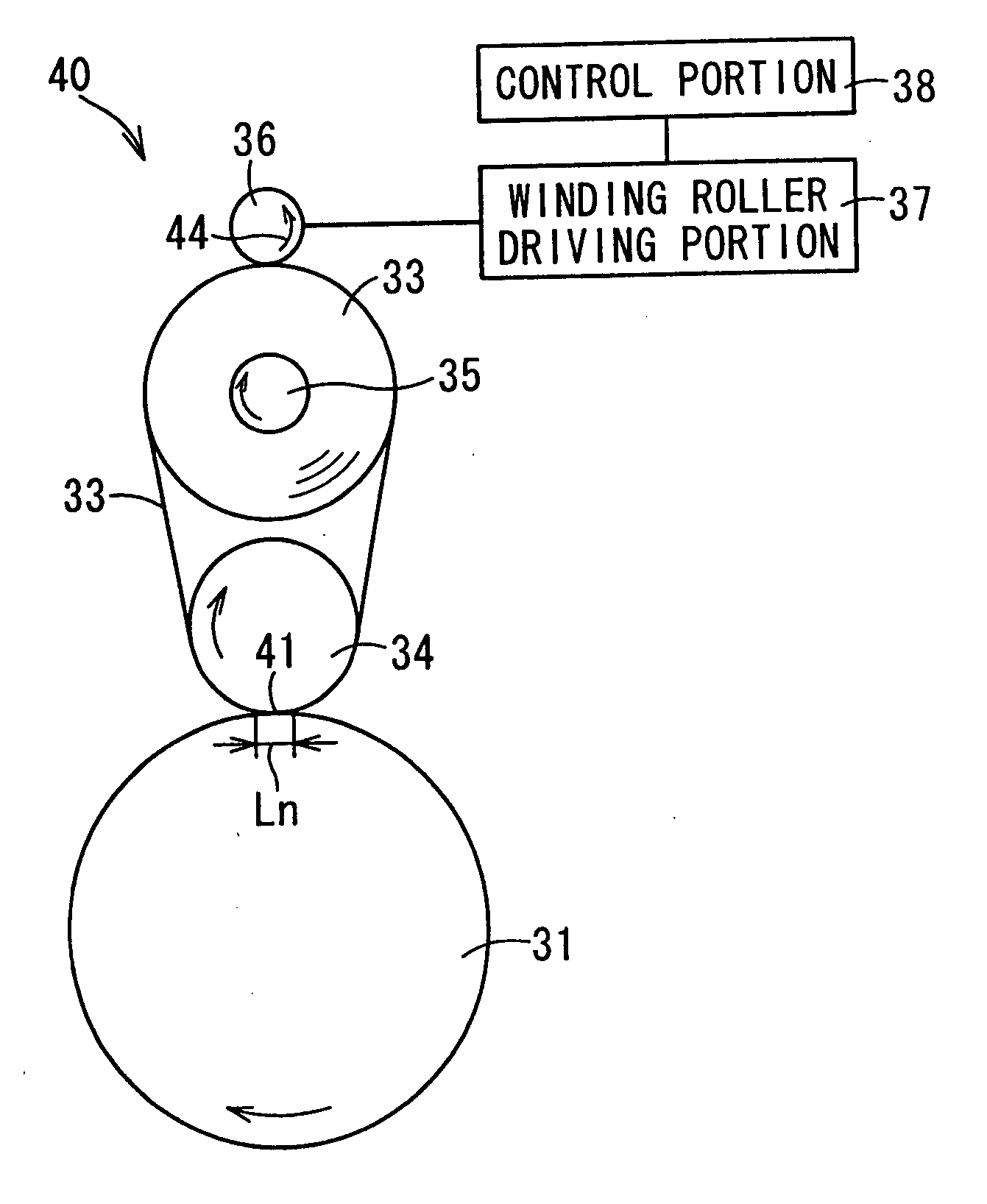
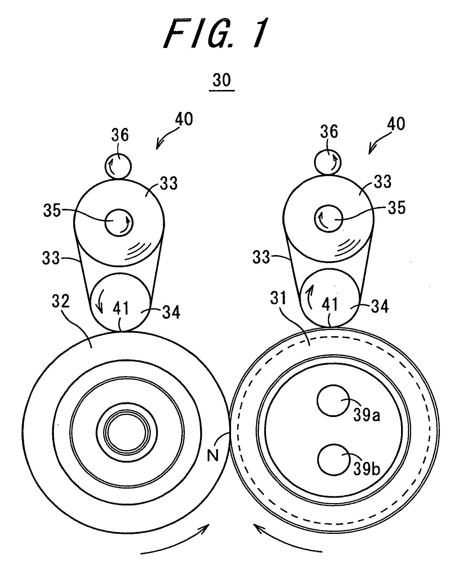
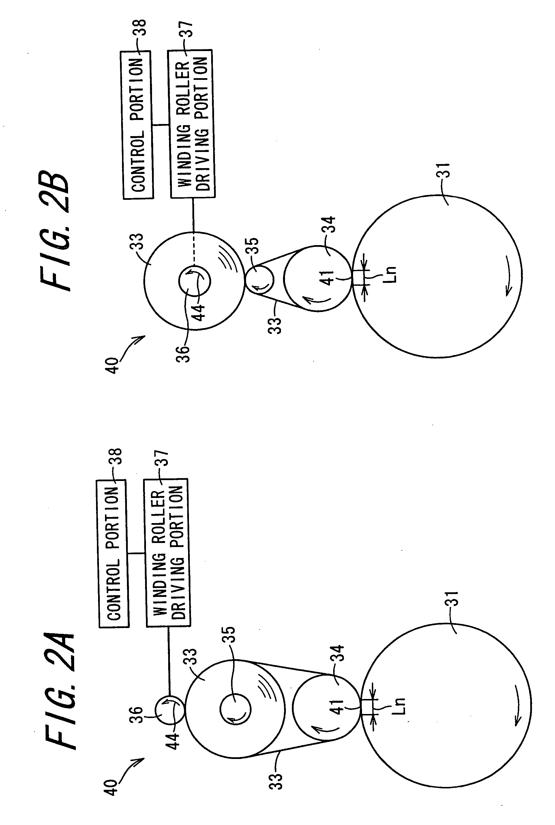
[0053]FIG. 1 is a schematic view showing a configuration of a fixing device 30 according to one embodiment of the invention. FIGS. 2A and 2B are enlarged views each showing a fixing roller cleaning unit 40 provided around a heating roller 31 in the fixing device 30 shown in FIG. 1.

[0054] The fixing device 30 comprises a heating roller 31; a pressure roller 32; a belt-shaped cleaning member 33; a pressure-contact roller 34; a feeding roller 35; a winding roller 36; a winding roller driving portion 37; and a control unit 38. The heating roller 31 and the pressure roller 32 are formed of a pair of rotators, and constitute fixing rollers. The belt-shaped cleaning member 33 is provided so as to contact the heating roller 31 and the pressure roller 32, respectively, and cleans surfaces of the fixing rollers. The pressure-contact roller 34 is provided so that a nip section 41 serving as a pre...


PUM


Abstract

A fixing device includes a feeding roller for feeding a belt-shaped cleaning member which has been rolled up, and a winding roller for taking up the cleaning member which has been fed from the feeding roller and cleaned a surface of the fixing roller, the winding roller being provided so as to pressure-contact the feeding roller. The winding roller is rotated by a time control due to a control portion so that a sum of a feed amount of the cleaning member which is fed by the feeding roller at one feeding occasion, and a take-up amount of the cleaning member which is taken up by the winding roller at one take-up occasion, is equal to or more than a double of a length Ln of a nip section.

Description

BACKGROUND OF THE INVENTION [0001] 1. Field of the Invention [0002] The present invention relates to a fixing device favorably for use in an electrophotographic image forming apparatus, and to an image forming apparatus having the same. [0003] 2. Description of the Related Art [0004] In an image formation using an electrophotographic system, a photoreceptor charged with a uniform electric potential is exposed to light in accordance with image information so that an electrostatic latent image is formed. The formed electrostatic latent image is developed by a developer so as to be visualized. The visualized image is transferred on a recording paper or the like, and the transferred developer on the recording paper is made to be fixed so as to form a solid recording image. [0005] The fixing device used for such image formation, is generally composed of a heating roller and a pressure roller. The fixing device has such a configuration that, in passing the recording paper on which the dev...

Claims


Application Information

Patent Timeline
Patent Type & Authority Applications(United States)
IPC IPC(8): G03G15/20
CPCG03G2215/2016G03G2215/2032G03G15/2025
Inventor MIKITA, TOSHIYAMINAKUCHI, YASUNORITATEISHI, YOSHINOBUHORI, HIROAKIIDE, ATSUSHI
Owner SHARP KK
Why Eureka
Try Eureka