
Holster manufacturing system and method of making

a manufacturing system and holster technology, applied in the field of plastic handgun holster manufacturing, can solve the problems of high initial mold cost, high cost of plastic handgun molds, and high cost of injection molds for each shap

Inactive Publication Date: 2006-07-20
TACTICAL DESIGN LABS
View PDF13 Cites 42 Cited by
  • Summary
  • Abstract
  • Description
  • Claims
  • Application Information

AI Technical Summary

Benefits of technology

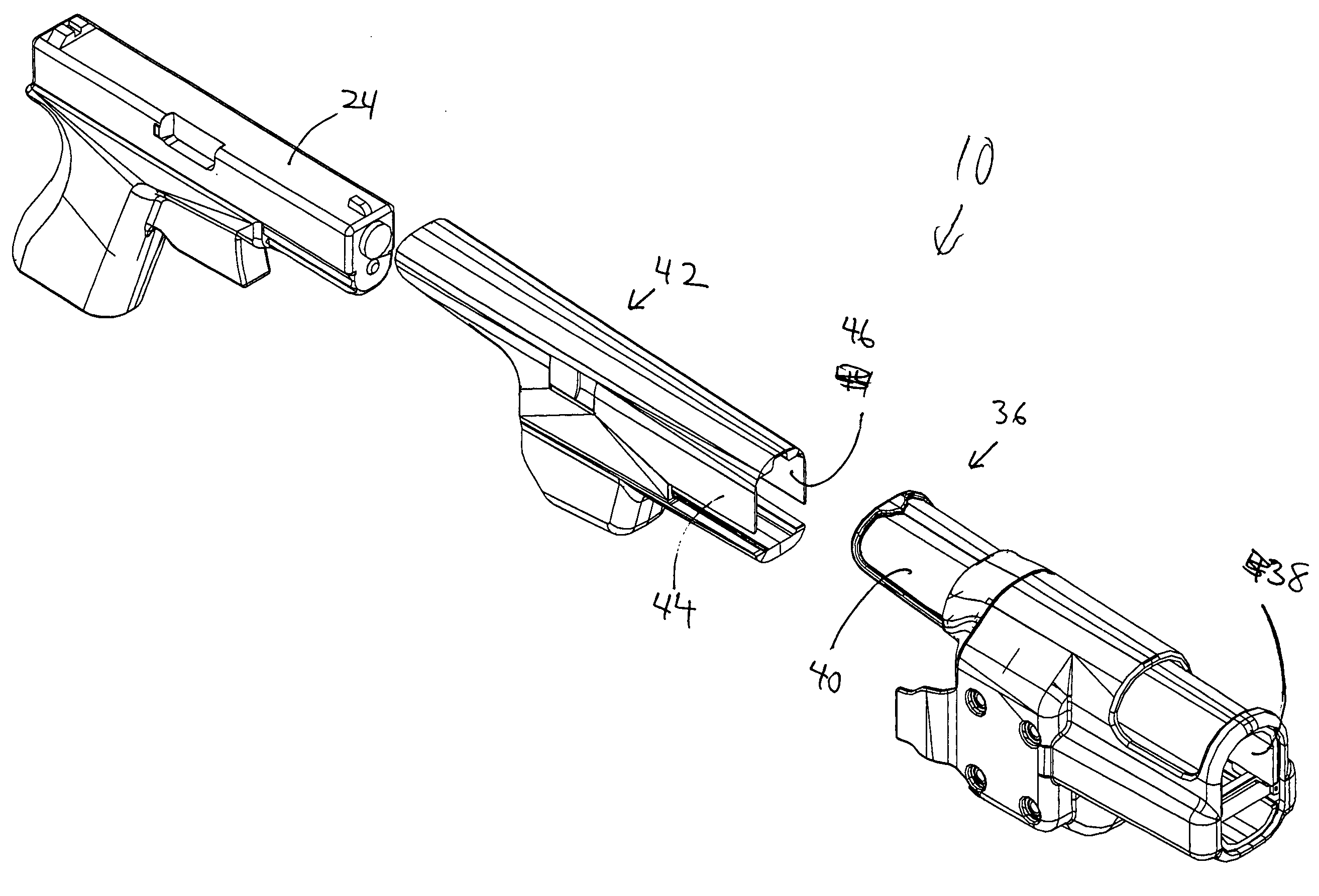
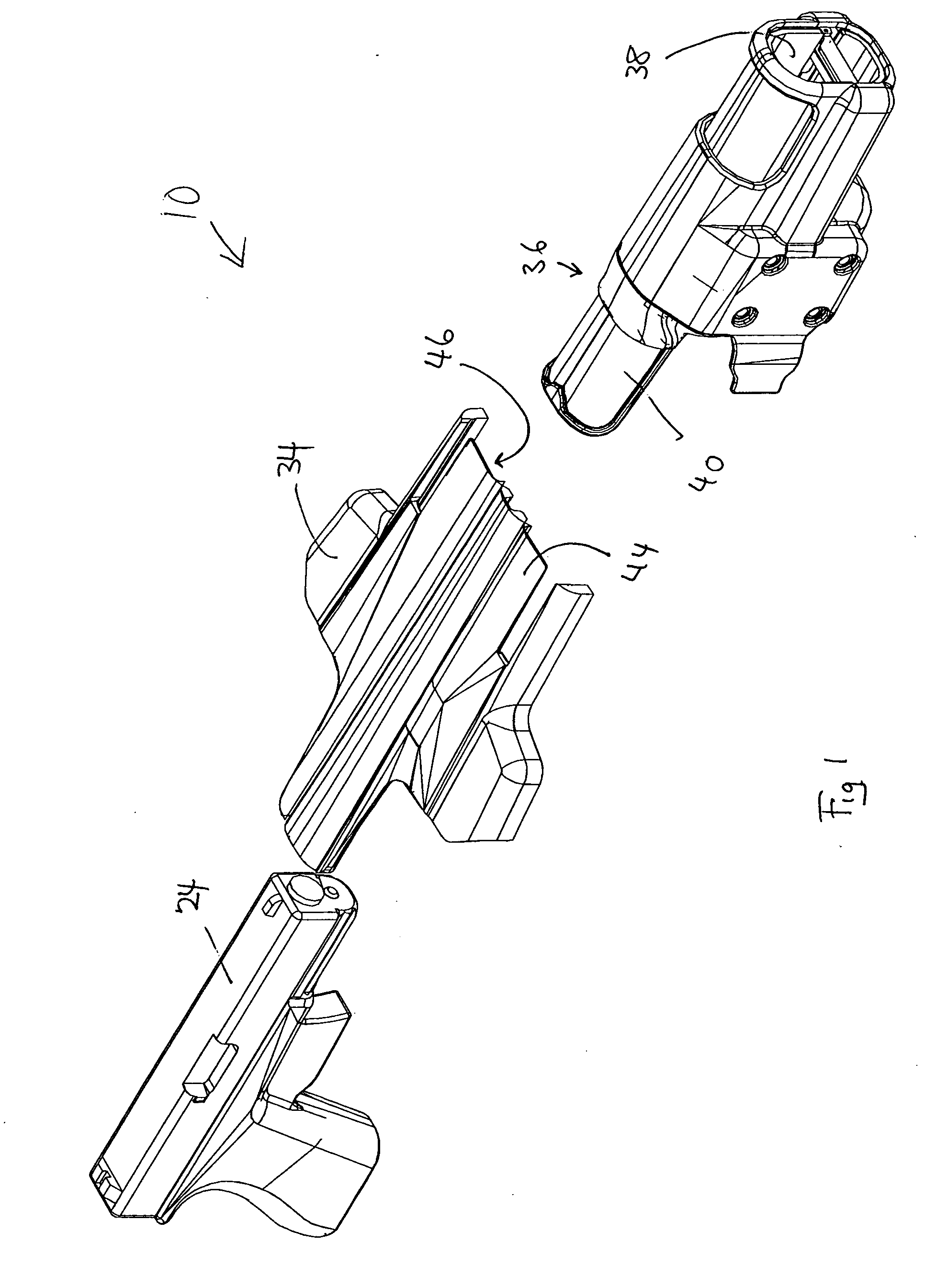
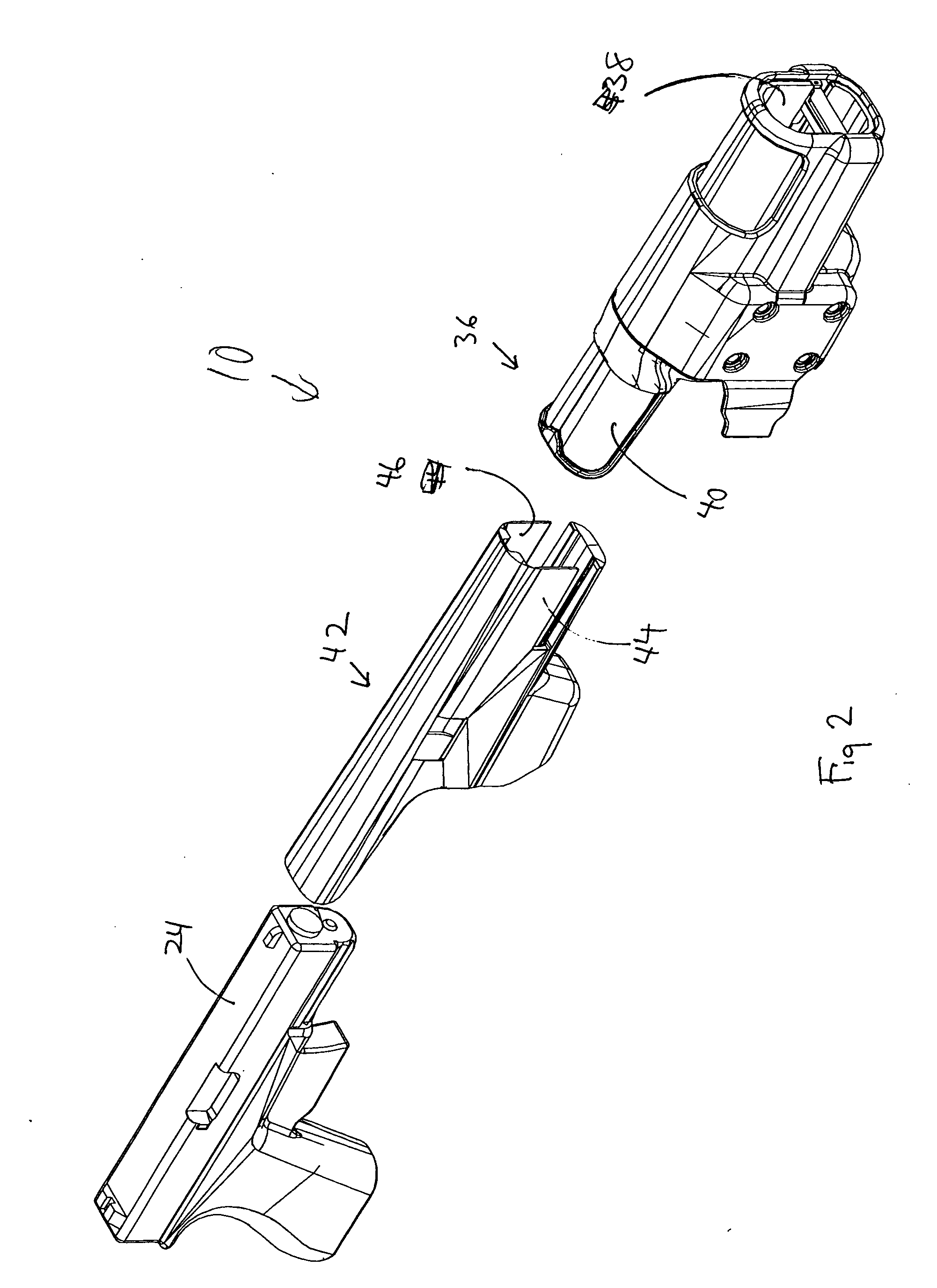
[0008] The invention is a method of manufacturing handgun holsters which are suitable for use with a number of different sizes of gun models, with a process that does not require a completely different mold for injecting plastic for each different shape of gun. One version of the invention is accomplished by first configuring an outer shell of the handgun made of molded plastic. The outer shell has an inner surface and an outer surface, with the outer surface having the desired holster exterior features and the inner surface being configured to fit with a number of inner shells, with the inner shells each specifically configured for different handguns. The inner shells are also made of molded plastic, and each have an exterior surface designed for engagement with the inner surface of the outer shell, and each of the inner shells have an interior surface which is designed for close tolerance interfitting engagement with the surface features of a selected handgun. The inner shell is specifically selected for a specific handgun, and its interior surface is designed for a close tolerance fit to that handgun. The outer shell and the inner shell are joined together to form a molded plastic handgun holster which has the desired external features and also which has an interior surface which closely interfits with the surface features of a selected handgun. By utilizing a different inner shell, a plastic handgun holster can be manufactured for a different model merely by changing the configuration and selection of the inner shell. Just changing the inner surface of the finished handgun is much easier than having to retool to make both the inner surface and the outer surface in a separate injection mold for each handgun.
[0012] One configuration of the mold core which is desirable and which would reflect in corresponding structures in the holster interior is a series of ridges and grooves on the mold core. The interstices between the ridges provide a space into which liquid material fills, resulting in projecting fins on the interior of the holster. These fins on the holster interior provide a contact area for the handgun as it moves in and out of the holster. The fins are preferred over flat surfaces because they result in less resistance to inserting and extracting the handgun, while maintaining a close tolerance fit around the features of the handgun.
[0013] Another advantage of using ribs on a core for creating an inner mold would be that a core for a small handgun would result in relatively longer ribs extending from the inner shell to contact the handgun. For a different model of handgun, a new core could be formed by trimming down the ribs. Thus, one core could serve as a basis for more than one handgun.

Problems solved by technology

A problem with a plastic handgun holster which has close tolerances and which is made to fit closely with a handgun is that the mold for making the plastic handgun is very expensive.
Once the mold is made, then handguns can be made quite inexpensively, but the initial mold is expensive.
A plastic holster which is made to have a close tolerance fit with one handgun, might be too tight for another handgun, or it may allow a different handgun to be held too loosely within the holster.
There are hundreds of different handgun shapes, and making an injection mold for each shape is quite expensive, if not prohibitive.

Method used


Image

  • Holster manufacturing system and method of making
  • Holster manufacturing system and method of making
  • Holster manufacturing system and method of making

Examples


Embodiment Construction

[0021] While the invention is susceptible of various modifications and alternative constructions, certain illustrated embodiments thereof have been shown in the drawings and will be described below in detail. It should be understood, however, that there is no intention to limit the invention to the specific form disclosed, but, on the contrary, the invention is to cover all modifications, alternative constructions, and equivalents falling within the spirit and scope of the invention as defined in the claims.

[0022]FIGS. 1 through 5 shows several preferred embodiments of the method of manufacturing of the invention. The invention is a method of manufacturing of injected molded plastic handgun holsters which can accommodate a variety of sizes of handguns without making an entirely new injection mold. As shown in FIG. 1, in one version of the invention, the holster 10 can be made of two pieces. An outer shell 36 is of a uniform size and an inner shell 42 is utilized which can be placed...


PUM

PropertyMeasurementUnit
sizesaaaaaaaaaa
chemicalaaaaaaaaaa
sonic energyaaaaaaaaaa

Abstract

The invention is a method of manufacturing plastic holsters for handguns which utilize a standardized outer shell which is bonded with an inner shell. The interior surface of the inner shell is configured to correspond to the surface features of a handgun. The inner shell is bonded to the outer shell to form one unitary piece. A mold core may be used, with the core including ridges which form ribs in the inner surface of the holster or the inner shell of the holster, with the ridges being closely configured to match the surface features of the specific handgun for which it is adapted. By modifying the depth of the grooves between ridges on the core, interior surfaces for holsters for various models of handguns can be quickly and inexpensively designed.

Description

CROSS-REFERENCE TO RELATED APPLICATIONS [0001] This application claims the priority date of the provisional application entitled HOLSTER MANUFACTURING SYSTEM AND METHOD OF MAKING filed by Taylor Jenkins, et al., on Oct. 1, 2004 with application Ser. No. 60 / 615,183, the disclosure of which is incorporated herein by reference.DESCRIPTION [0002] 1. Field of the Invention [0003] The invention relates to generally to a method of manufacture, and more specifically to a method of manufacture of plastic handgun holsters. [0004] 2. Background of the Invention [0005] Holsters for handguns have traditionally been made of leather. In recent times, certain types of plastic materials have proven to be very suitable for making holsters for handguns also. Some of these plastic materials are extremely durable and can be manufactured by methods suitable for mass production of plastics. These methods include injection molding, and other types of manufacturing suitable for plastics, which would not wor...

Claims


Application Information

Patent Timeline
Patent Type & Authority Applications(United States)
IPC IPC(8): B23Q17/00F41C33/00
CPCF41C33/0209Y10T29/49826Y10T29/4978
Inventor JENKINS, TAYLORSENN, TONYLOWE, MIKE
Owner TACTICAL DESIGN LABS
Learn More