
Plasma display apparatus

a technology of display apparatus and plasma, which is applied in the direction of instruments, static indicating devices, casings/cabinets/drawer details, etc., can solve the problems of reducing productivity, scarcely using every signal-input terminal, and affecting the productivity of users in the consumer market, etc., and achieves the effect of being prepared

Inactive Publication Date: 2006-07-06
PANASONIC CORP
View PDF2 Cites 2 Cited by
  • Summary
  • Abstract
  • Description
  • Claims
  • Application Information

AI Technical Summary

Benefits of technology

[0020] This structure allows for the preparation of a number of block units having an input terminal section responsive to an external apparatus to be coupled to the plasma display apparatus. The block unit can be replaced with another one that is responsive to a user's request, so that the plasma display apparatus equipped with a signal input terminal appropriate to an application can be prepared with ease.

Problems solved by technology

Users in the consumer market, however, scarcely use every signal-input terminal, but use one specific terminal for a particular external apparatus.
Therefore, a number of the various signal-input terminals are useless for the users in the consumer market.
However, there will be a lot of models of one product because of the many applications discussed above, which lowers the productivity.

Method used


Image

  • Plasma display apparatus
  • Plasma display apparatus
  • Plasma display apparatus

Examples


case 34

[0059] Case 34 includes second block-unit 39 therein having second input terminal 38 to which a connection cable, for coupling to another external apparatus such as a tuner or a personal computer, is detachably coupled. Second signal outputting connector 40 is always coupled to signal inputting connector 32 of control circuit block 23. Case 34 is omitted in FIG. 6, and first input terminal 36 and second block-unit 39 are omitted in FIG. 7.

[0060] Case 34 is formed by bending a metal plate, and as shown in FIG. 7 and FIG. 8, the face thereof opposite to chassis 14 includes tabs 41 unitarily formed with case 34 and disposed at various places. Tab 41 has a mounting hole 41a through which a screw extends for mounting case 34 to chassis 14. Another face of case 34 substantially vertical to the mounting face discussed above includes mounting port 33 and terminal port 43. Terminal port 43 has openings 42 to which second input-terminal 38 of second block unit 39 built in case 34 are placed. ...


PUM


Abstract

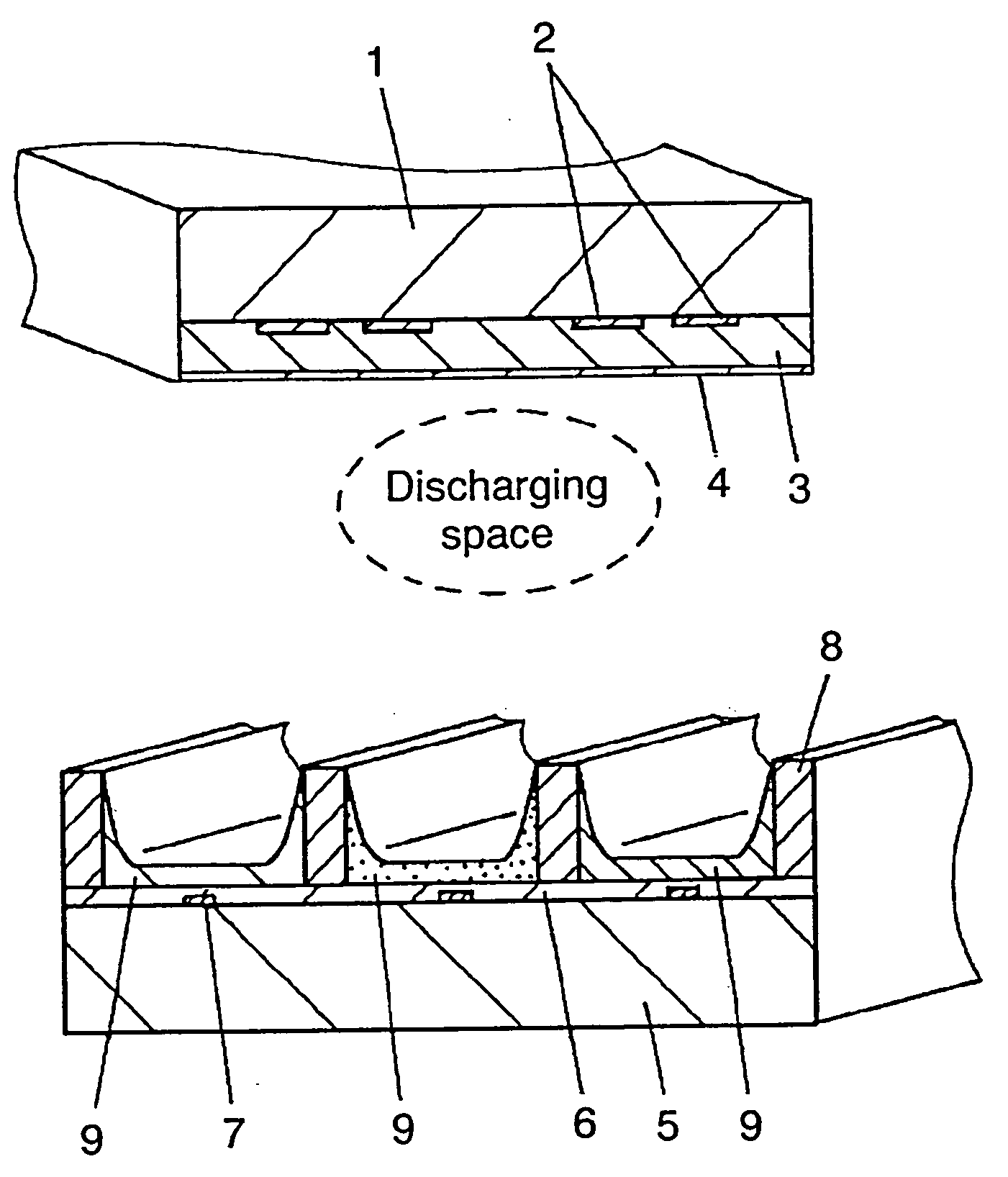
A plasma display apparatus is equipped with a signal input terminal responsive to a user's application. The plasma display apparatus includes a panel including a pair of substrates, wherein at least one of the substrates is transparent. The substrates are placed opposite to each other to form a discharge space in between, and electrodes are provided to the substrate. The plasma display apparatus also includes a display driving circuit block, disposed on a chassis and equipped with at least one signal inputting connector which applies a signal to the panel to perform displaying, and an input signal circuit block detachable to the signal inputting connector of the display driving circuit block.

Description

[0001] This application is a divisional application of application Ser. No. 10 / 311,433, which is a U.S. national stage application of International Application Serial No. PCT / JP02 / 05841, filed Jun. 12, 2002.TECHNICAL FIELD [0002] The present invention relates to plasma display apparatuses which are thin, light weight, and have a large display area. BACKGROUND ART [0003] Plasma display apparatuses are widely used as display apparatuses installed in busy sections of a city for the general public, or installed at a home for a family to enjoy videos on a large screen. A plasma display panel (PDP) has better characteristics than a liquid crystal panel in the following points: responding at a faster speed, a wider viewing angle, easier to produce a larger screen, and higher display quality due to self-light-emitting. [0004] In the PDP, display cells partitioned with barrier ribs are disposed on a board, and a phosphor layer covers the display cells. An ultraviolet ray generated by gas dis...

Claims


Application Information

Patent Timeline
Patent Type & Authority Applications(United States)
IPC IPC(8): H01J17/49H01J11/46G09G3/28G09G5/00H05K5/02
CPCH05K5/02H01J11/46
Inventor NOMOTO, TOMIHIDEKOJIMA, KAZUNOBUMIZUNO, AKIRA
Owner PANASONIC CORP
Learn More