
Heart rate monitor

Inactive Publication Date: 2006-06-29
TIMEX GROUP
View PDF7 Cites 99 Cited by
  • Summary
  • Abstract
  • Description
  • Claims
  • Application Information

AI Technical Summary

Benefits of technology

[0009] Another objective of the present invention is to provide a heart rate monitor that is comfortable to wear, and which provides accurate heart rate information.
[0010] Another object of the present invention to provide a heart rate monitor that can be worn about a user's head, such as in a heart rate monitor that incorporates a display that may be provided in the headset itself.

Problems solved by technology

In the medical field, heart rates may be monitored in a variety of ways, most of which are prohibitive in the area of the “fitness world” due to the physical nature of athletic activities.
However, it is perceived that there are disadvantages of using the finger as a source of the pulse wave detection, such as unreliability of results via inaccurate pulse wave detections, and discomfort during vigorous exercise.
Similar discomfort is a perceived disadvantage in using the cheststrap unit as well.

Method used


Image

  • Heart rate monitor
  • Heart rate monitor
  • Heart rate monitor

Examples


Embodiment Construction

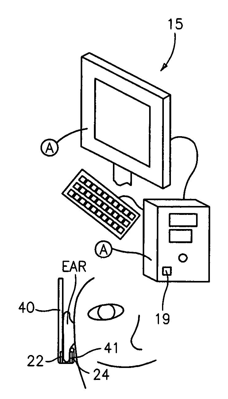
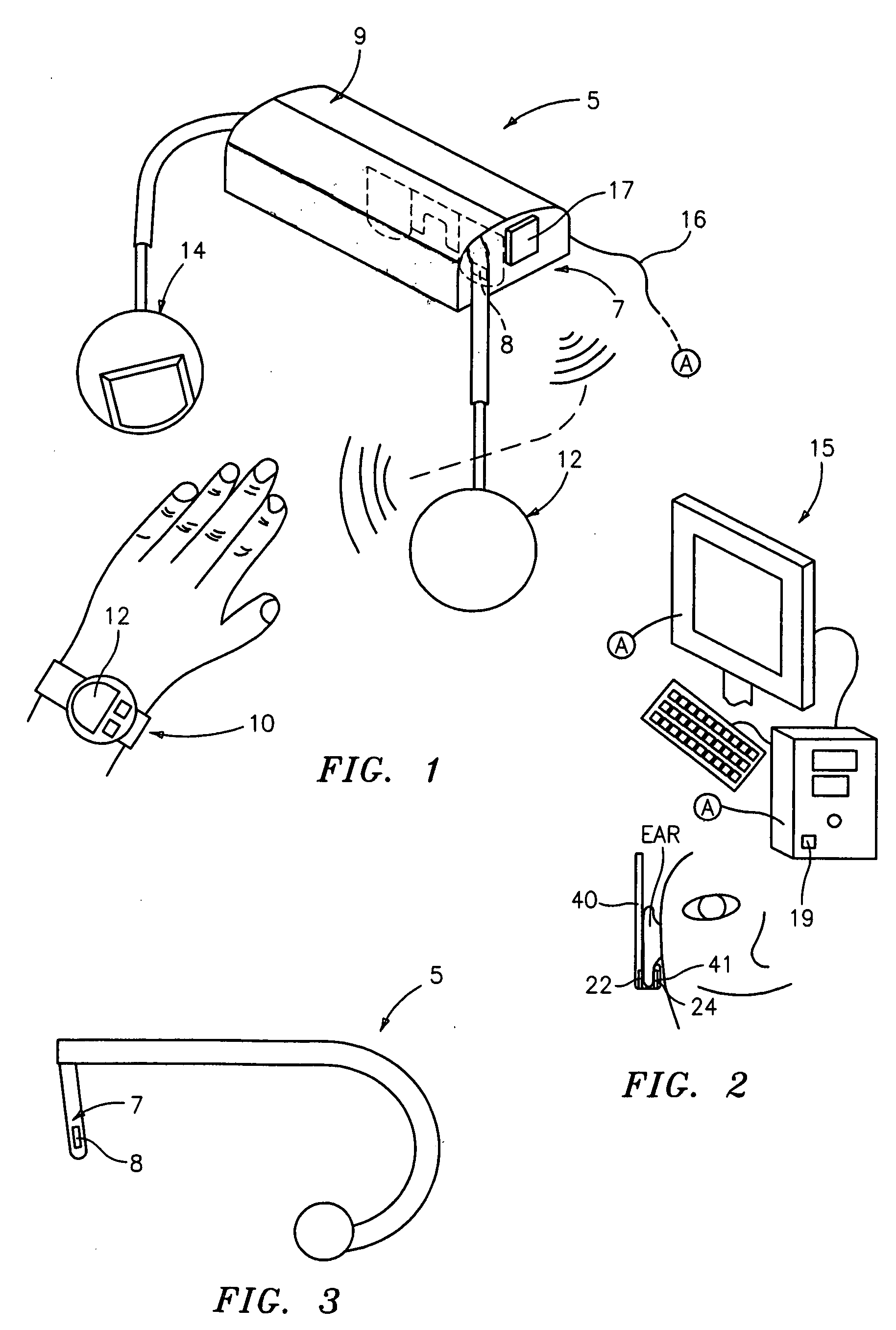
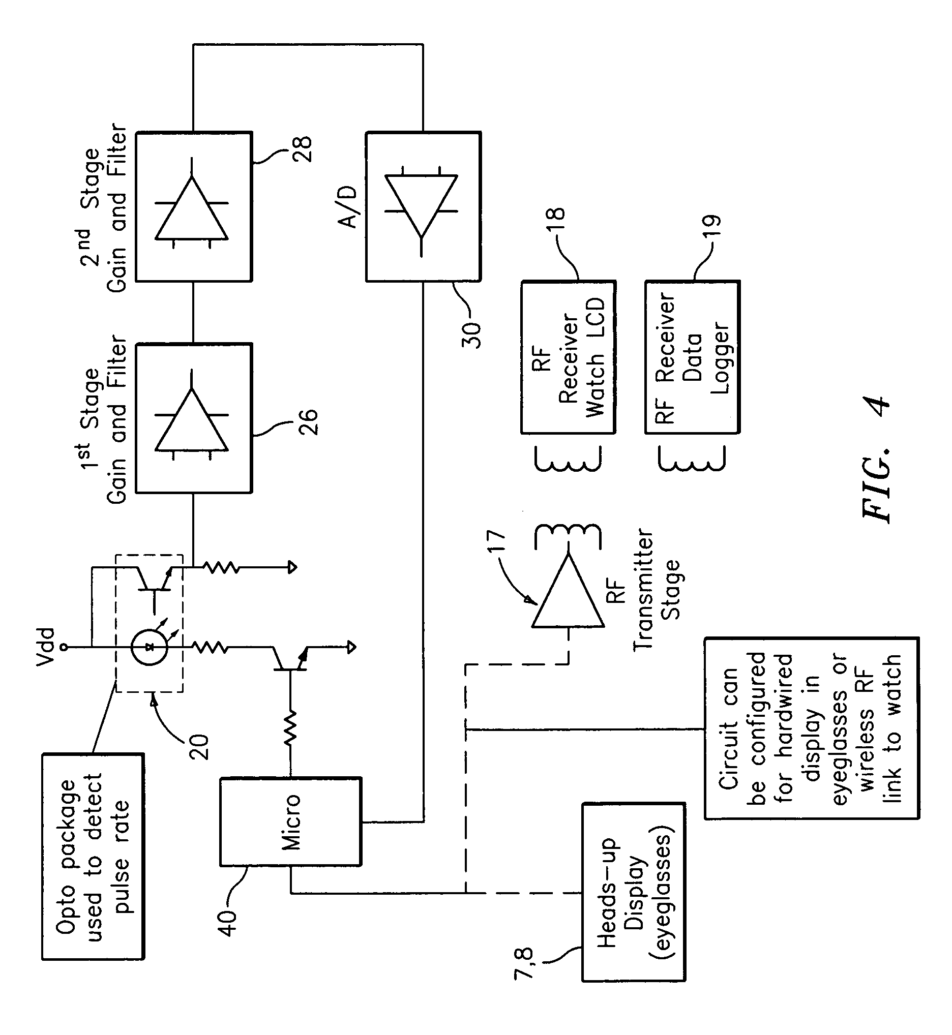
[0026] Reference shall first be made to FIGS. 1-3 for an overall disclosure of the heart rate monitor and system constructed in accordance with the present invention. Specifically, comprising the wearable heart rate monitor of the present invention is a headset unit, generally indicated at 5. As will be more fully appreciated below, the heart rate monitor of the present invention (hereinafter the “HRM” for ease of reading) comprises a display for displaying the heart rate to a user.

[0027] Three types of wearable displays are contemplated herein and are in accordance with the preferred embodiments. The first embodiment comprises a visor with a built-in display, such as LCD. Such an exemplary construction, generally indicated at 7 and including a display unit 8, is illustrated in FIG. 1 as being depending from a headpiece unit, generally indicated at 9. A similar display unit 8 is shown in FIG. 3, which itself illustrates another design configuration for carrying the circuitry and wi...


PUM


Abstract

A wearable fitness heart rate monitor comprising an earpiece comprising a sensor unit having a light emitting element and a light receiving element, wherein a portion of an ear is positioned therebetween, wherein the light emitting element emits light into the portion of the ear positioned intermediate the light emitting and light receiving elements, the light receiving element detects the intensity of light passing through the portion of the ear positioned intermediate the light emitting and light receiving elements, and the sensor unit comprises means for outputting an electrical signal based thereon; processor means, coupled to the sensor unit, for processing the electrical signal and determining a heart rate therefrom; and a display, coupled to the processor means, for displaying the heart rate. Alternatively, the transmitting element (LED) and the receiving element (photodiode or the like), are positioned adjacent each other, such that the transmitting element emits light into the portion of the ear and the receiving element receives reflected light therefrom, and wherein the sensor unit detects the intensity of the reflected light and outputs electrical signals based thereon.

Description

BACKGROUND OF THE INVENTION [0001] The present invention relates generally to heart rate monitors, and in particular, to a heart rate monitor that detects one's heart rate from a sensor located about the ear so that a least a portion of the heart rate monitor, namely, at least the portion via which the pulse rate is detected, may be worn about the head, such as in the form of a headset. [0002] Heart rate monitors are well known, being used in a variety of fields of endeavor, including the medical and fitness fields. In the medical field, heart rates may be monitored in a variety of ways, most of which are prohibitive in the area of the “fitness world” due to the physical nature of athletic activities. [0003] That is, in the “fitness world,” popular heart rate monitors typically come in the form of a two-piece “system” comprising a cheststrap, which (at least) detects the heartbeat, and a wrist worn unit, which is typically used to display a calculated heart rate. Such designs are wi...

Claims


Application Information

Patent Timeline
IPC IPC(8): A61B5/02
CPCA61B5/0002A61B5/02416A61B5/02438A61B5/6815A61B5/6816A61B5/742
Inventor GARAY, JOHN L.GALIE, LOUIS M.SIMONEAU, DANKEITHLINE, WILSON W.
Owner TIMEX GROUP
Learn More