
Universal scissors joint apparatus

Active Publication Date: 2006-06-29
THOMPSON SURGICAL INSTR
View PDF4 Cites 70 Cited by
  • Summary
  • Abstract
  • Description
  • Claims
  • Application Information

AI Technical Summary

Benefits of technology

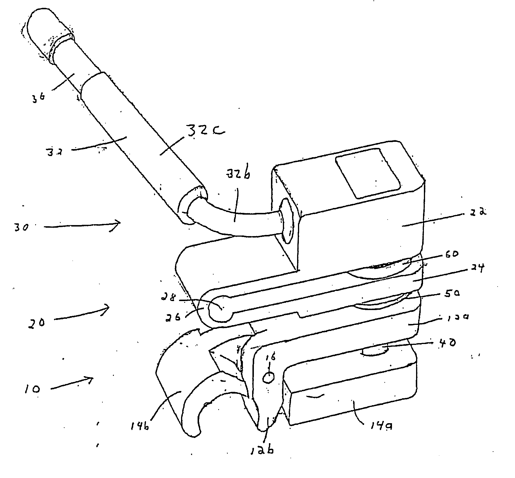
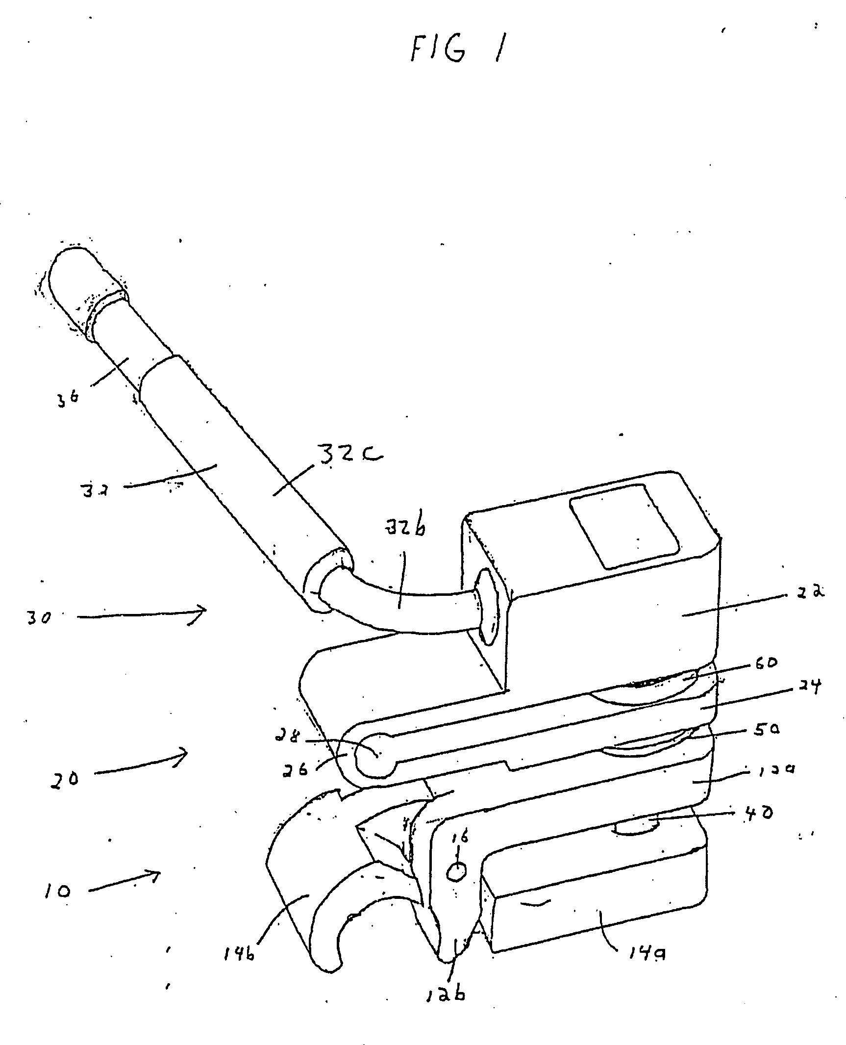
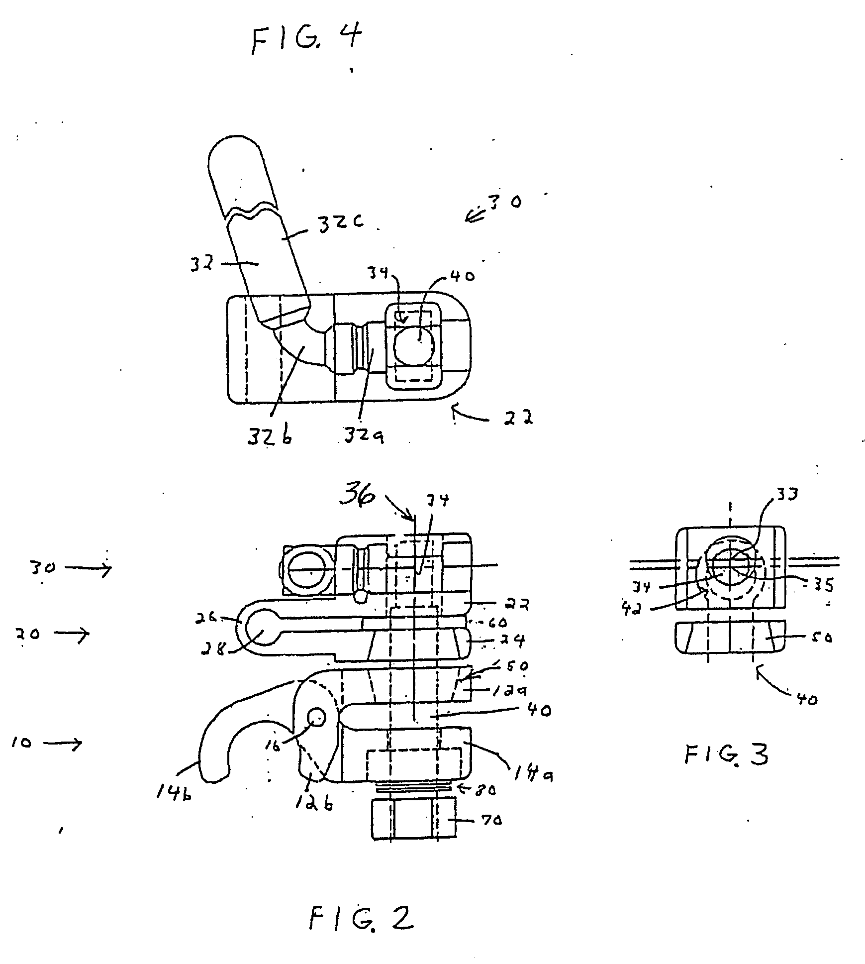
[0013] The present invention provides a universal joint apparatus. The present invention comprises clamps, a locking mechanism, and a rod associating the clamps with the locking mechanism. At least one clamp is a scissors clamp, i.e. a clamp comprising a first segment and a second segment, with the segments fastened by a pivot. The scissors clamp generates extra compressive force on the object being held, providing a stable and rigid universal joint. Clamps are able to rotate with respect to each other, allowing for greater flexibility in usage. The present invention is capable of being added to a support frame between other components. In one embodiment of the invention, the universal joint apparatus includes an integrated retractor blade handle, which, in conjunction with the cam locking mechanism, ensures that the locked position of the cam handle is oriented substantially away from the operating field.

Problems solved by technology

Surgical operations often require prolonged access to the internal anatomy of a patient.
Many previous universal joints have separable components which require more care and effort for sterilization due to the need to disassemble and reassemble the components.
Unfortunately, the manipulation of the cam locking mechanism often results in the cam handle being oriented towards, and into, the operative site, thereby potentially interfering with a surgeon's visual access to the patient's anatomy or physically intruding with a surgeon's movement.
However, this freedom of movement may create unnecessary obstacles for the surgeon or create an additional issue that a surgical staff must consider and address.
Furthermore, the lack of an integrated retractor blade handle increases the difficulty and time required for setting up and positioning the retractor blade relative to the patient's anatomy.

Method used


Image

  • Universal scissors joint apparatus
  • Universal scissors joint apparatus
  • Universal scissors joint apparatus

Examples


Embodiment Construction

[0026]FIG. 10 illustrates the use of conventional universal joints in a surgical retraction system 101. Adjustable clamps 223, 225 are secured, through the use adapters 140, 145, to the frames 150, 155 of a conventional framed stretcher 160. A post 170 extends vertically from a clamp 223 to provide support for a cross bar 180, which in turn provides support for a pair of extension arms 190, 200. The crossbar 180 is secured to the post 170 by a universal joint clamp 210. The extension arms 190, 200 are secured to the cross bar 180 by a pair of universal joint clamps 220, 240. Additional universal joint clamps 260, 280 are disposed along the extension arms 190, 200 for rigidly securing any number of retractor blades 340, 360 to the extension arms 190, 200.

[0027] The universal joints 260, 280 allow for both the rotation of the clamping mechanism along the longitudinal axis of the extension arms 190, 200 and the pivotable placement of the retractor blade handle 440 in relation to the e...


PUM


Abstract

A universal joint apparatus comprises clamps, a locking mechanism, and a rod connecting the clamps and the locking mechanism. At least one clamp is a scissors clamp, i.e. a clamp comprising two segments fastened by a pivot. The scissors clamp generates extra compressive force on the object being held, providing a stable and rigid universal joint. Clamps are able to rotate with respect to each other, allowing for greater flexibility in usage. The universal joint apparatus is capable of being added to a support frame between other components. In one embodiment of the invention, the universal joint includes a dedicated retractor blade handle to ensure that the locked position of the cam handle is oriented substantially away from the operative site.

Description

RELATED APPLICATION [0001] This application is a continuation of application Ser. No. 10 / 365,822, filed on Feb. 13, 2003, now abandoned, which is a continuation-in-part of application Ser. No. 10 / 164,487, filed Jun. 6, 2002, now abandoned. The foregoing applications are hereby incorporated by reference herein in their entirety, including the specification, claims, drawings and abstract.BACKGROUND OF THE INVENTION [0002] The present invention relates to surgical apparatus for retracting a patient's anatomy during an operation to provide exposure of the operative site. More particularly, the present invention relates to a universal scissors joint apparatus that is sturdy, stable, readily adjustable, and easily sterilized. [0003] Surgical operations often require prolonged access to the internal anatomy of a patient. Retractors are used to hold back tissue around the surgical site, granting the surgeon the needed access. While hand-held retractors may be used during surgeries, it is of...

Claims


Application Information

Patent Timeline
IPC IPC(8): A61B1/32A61B17/02A61B17/28A61B19/00
CPCA61B17/02A61B17/2812A61B19/26A61B2017/2913A61B90/50
Inventor MULAC, ANTHONY J.FARLEY, DANIEL K.
Owner THOMPSON SURGICAL INSTR
Learn More