Fuel cell system
a fuel cell and system technology, applied in the field of fuel cell systems, can solve the problems of reducing durability, affecting the overall size of the fuel cell power generation apparatus, and affecting the durability of the pre-reformer b>3/b>, so as to reduce the overall size of the fuel cell system
- Summary
- Abstract
- Description
- Claims
- Application Information
AI Technical Summary
Benefits of technology
Problems solved by technology
Method used
Image


Examples
first embodiment
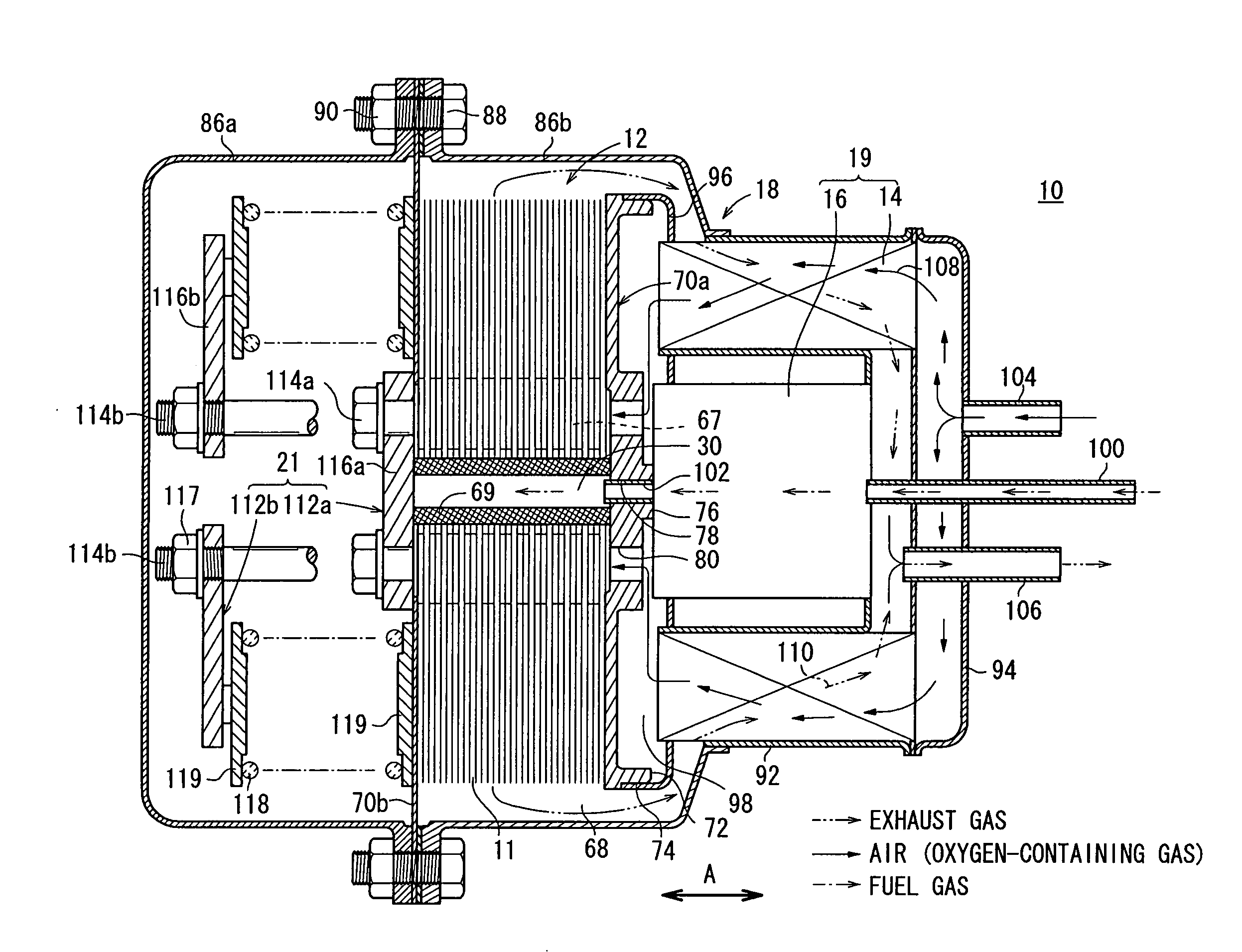
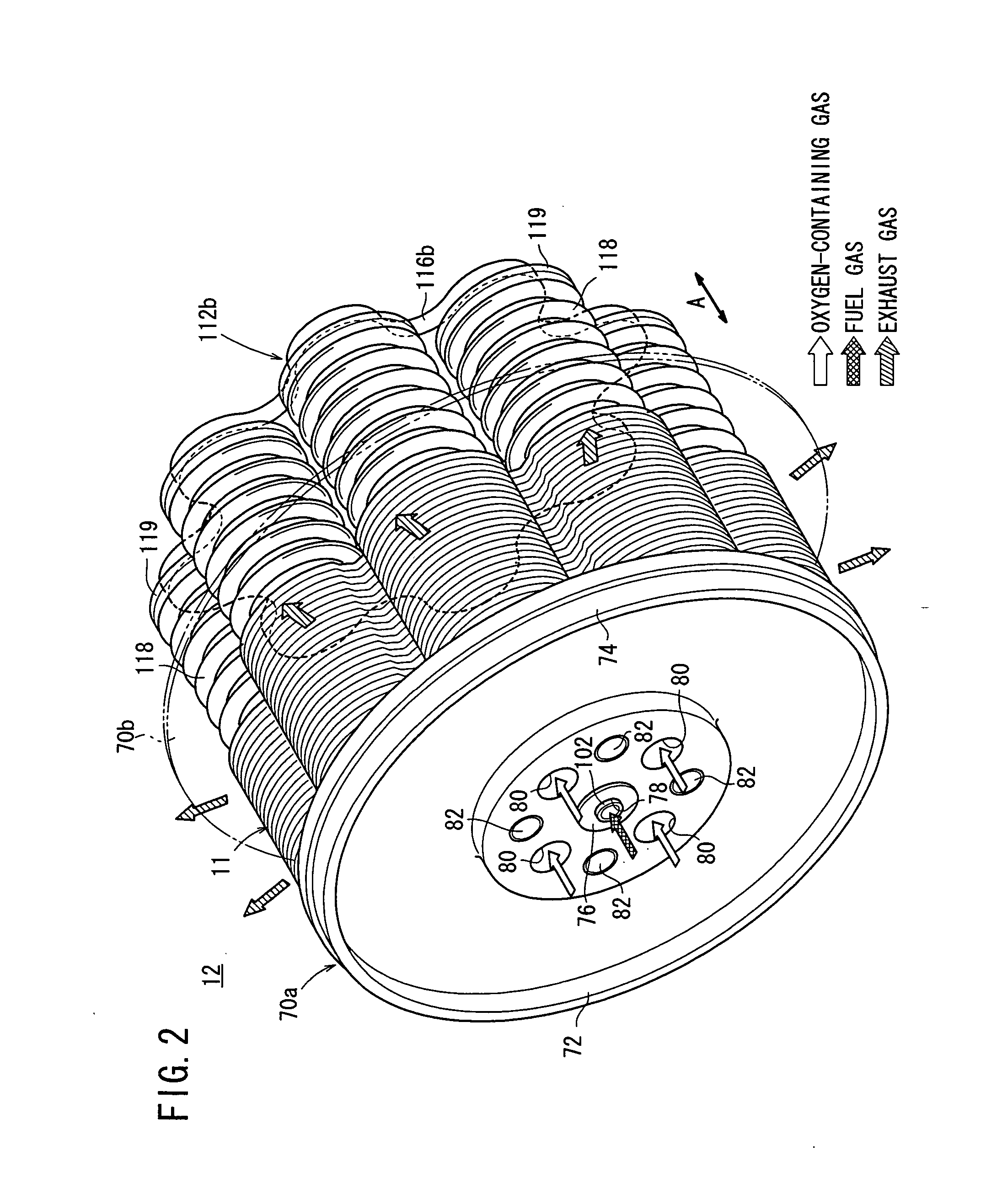
[0047]FIG. 1 is a partial cross sectional view showing a fuel cell system 10 according to the present invention. FIG. 2 is a perspective view schematically showing a fuel cell stack 12 of the fuel cell system 10. The fuel cell stack 12 is formed by stacking a plurality of fuel cells 11 in a direction indicated by an arrow A.
[0048] The fuel cell system 10 is used in various applications, including stationary and mobile applications. For example, the fuel cell system 10 is mounted on a vehicle. As shown in FIG. 1, the fuel cell system 10 includes the fuel cell stack 12, a heat exchanger14, a reformer 16, and a casing 18. The heat exchanger 14 heats the oxygen-containing gas before it is supplied to the fuel cell stack 12. The reformer 16 reforms a fuel to produce a fuel gas. The fuel cell stack 12, the heat exchanger 14, and the reformer 16 are disposed in the casing 18.
[0049] In the casing 18, a fluid unit 19 including at least the heat exchanger 14 and the reformer 16 is disposed o...
second embodiment
[0099] In the second embodiment, the fuel gas supplied to the fuel gas supply passage 30 flows along the fuel gas supply channel 66 formed between each separator 28 and the channel member 124. Then, the fuel gas is supplied to the anodes 24 from the fuel gas inlets 128 formed at the ends of the channel member 124.
[0100] Thus, the fuel gas is supplied from the central regions to the outer regions of the anodes 24 even more suitably and uniformly, and power generation efficiency is improved. Further, since no fuel gas inlets are required in the circular disks 36 of the separators 28, the structure of the separator 28 is simplified, and reduction in the production cost is achieved easily.
third embodiment
[0101]FIG. 16 is a partial cross sectional view showing a fuel cell system 130 according to the present invention.
[0102] In the fuel cell system 130, the reformer 16 is provided inside the heat exchanger 14, and a partition wall 132 extending in a direction indicated by an arrow B is connected to the outer circumferential portion of the reformer 16 and the inner circumferential portion of the heat exchanger 14. The partition wall 132 is made of a substantially ring-shaped plate member.
[0103] A first channel member (oxygen-containing gas channel member) 134 is provided at the end plate 70a. The first channel member 134 protrudes coaxially with the protrusion 76. The first channel member 134 and the protrusion 76 protrude in the same direction indicated by the arrow A. The first channel member 134 has a ring shape, and the end of the first channel member 134 is positioned near the partition wall 132. By providing the first channel member 134, a first channel 136 is formed in the casi...
PUM
| Property | Measurement | Unit |
|---|---|---|
| ion-conductive | aaaaa | aaaaa |
| DC electric energy | aaaaa | aaaaa |
| heat radiation loss | aaaaa | aaaaa |
Abstract
Description
Claims
Application Information
 - R&D
- Intellectual Property
- Life Sciences
- Materials
- Tech Scout
- Unparalleled Data Quality
- Higher Quality Content
- 60% Fewer Hallucinations
Browse by: Latest US Patents, China's latest patents, Technical Efficacy Thesaurus, Application Domain, Technology Topic, Popular Technical Reports.
© 2025 PatSnap. All rights reserved.Legal|Privacy policy|Modern Slavery Act Transparency Statement|Sitemap|About US| Contact US: help@patsnap.com