Ink-feeding device and pressure-generating method
a technology of pressure generation and feeding device, which is applied in the field of pressure generation method and feeding device, can solve the problems of increasing the negative pressure in the printing head, affecting the recording quality, so as to improve the recording quality, improve the freedom degree of constructing the entire apparatus, and improve the recording quality
- Summary
- Abstract
- Description
- Claims
- Application Information
AI Technical Summary
Benefits of technology
Problems solved by technology
Method used
Image
Examples
example 1
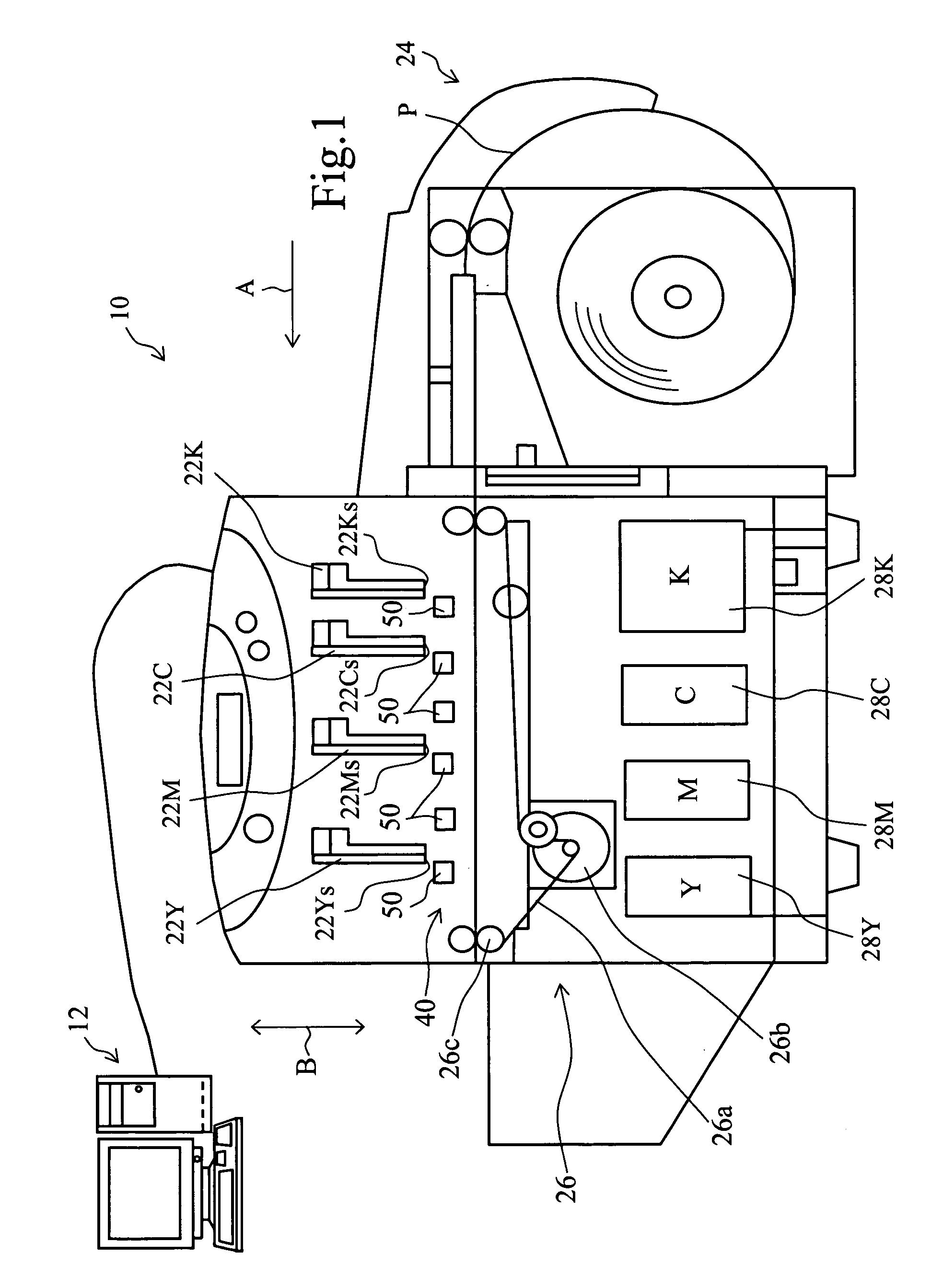
[0060] An example of the printer which incorporates the ink-feeding device of the present invention is explained by reference to FIG. 1.
[0061]FIG. 1 is a schematic front view of a printer incorporating an ink-feeding device of the present invention.
[0062] A printer 10 is connected to a host PC (personal computer) 12 for transmitting image information to this printer 10. In the printer 10, four printing heads 22K, 22C, 22M, 22Y are installed in a line in a direction (arrow-A direction) of delivery of a recording medium (a rolled paper sheet in this Example). The four printing heads 22K, 22C, 22M, 22Y eject respectively a color ink of black, cyan, magenta, or yellow. The four printing heads 22K, 22C, 22M, 22Y are so-called line-heads extending perpendicular to the paper sheet face of FIG. 1 (perpendicular to the arrow-A direction). The lengths of the four printing heads 22K, 22C, 22M, 22Y (length perpendicular to the paper sheet face of FIG. 1) are a little larger than the largest b...
example 2
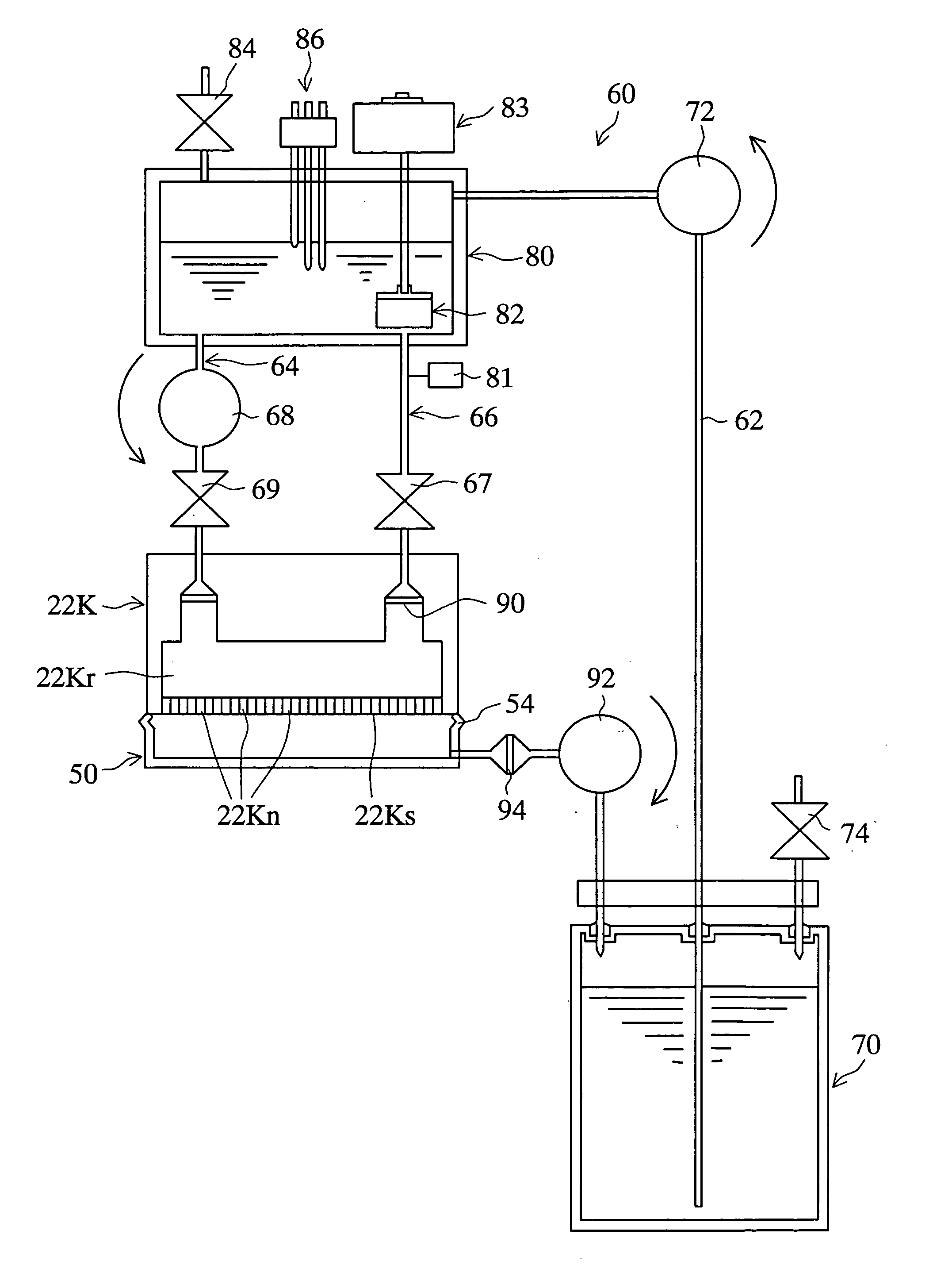
[0109] In Example 1, the sub-tank 80 is placed higher than the printing head 22K, but the placement is not limited thereto in the present invention. In this Example, an ink-feeding device 160 is explained in which the sub-tank 80 is placed lower than the printing head 22K by reference to FIG. 13.
[0110]FIG. 13 illustrates schematically the ink-feeding device of this Example 2. In this FIG. 13, the same reference numbers and symbols as in FIG. 3 are used for indicating corresponding elements.
[0111] In the ink-feeding device 160 in this Example 2, sub-tank 80 is placed lower than the printing head 22K. Even in such a positional relation, a pressure-adjusting pump 82 is useful for applying a positive pressure from the outside to keep a suitable negative pressure in the printing head 22K. In this Example, a centrifugal pump is used as the pressure-adjusting pump 82. The shape of the sub-tank 80 shown in FIG. 3 is not suitable for the centrifugal pump to apply sufficient positive pressu...
example 3
[0113] Example 3 is explained by reference to FIG. 14.
[0114]FIG. 14 is a schematic drawing of the ink-feeding device of this Example 3. In this drawing, the same reference numbers and symbols as in FIG. 6 are used for indicating corresponding elements.
[0115] In the above Example 1, the rotation frequency of the blade 82a (FIG. 7) of the pressure-adjusting pump 82 is changed for controlling the negative pressure in the printing head 22K. In contrast, in the ink-feeding device 170 of this Example 3, the shaft 172 is made movable vertically (in the arrow-D direction) with the blade 82a of the pressure-adjusting pump 82 fixed to the shaft 172. The pressure is controlled by changing the position of the blade 82a: the blade 82a is rotated at a constant rotation frequency by a driving unit 174.
[0116] The shaft 172 has a rack 172a. A pinion gear 172b is engaged with the rack 172a. The rotation of the pinion gear 172b is controlled by a CPU (FIG. 2). The driving force of the driving unit ...
PUM
 Abstract
Description
Claims
Application Information
 - R&D
- Intellectual Property
- Life Sciences
- Materials
- Tech Scout
- Unparalleled Data Quality
- Higher Quality Content
- 60% Fewer Hallucinations
Browse by: Latest US Patents, China's latest patents, Technical Efficacy Thesaurus, Application Domain, Technology Topic, Popular Technical Reports.
© 2025 PatSnap. All rights reserved.Legal|Privacy policy|Modern Slavery Act Transparency Statement|Sitemap|About US| Contact US: help@patsnap.com


