
System and method for coverage analysis in a wireless network

a wireless network and coverage analysis technology, applied in the field of wireless communication networks, can solve the problems of over-utilization of precious spectrum resources, difficult to plan such networks, and high associated costs of such deployments

Active Publication Date: 2006-06-15
BCE
View PDF10 Cites 115 Cited by
  • Summary
  • Abstract
  • Description
  • Claims
  • Application Information

AI Technical Summary

Benefits of technology

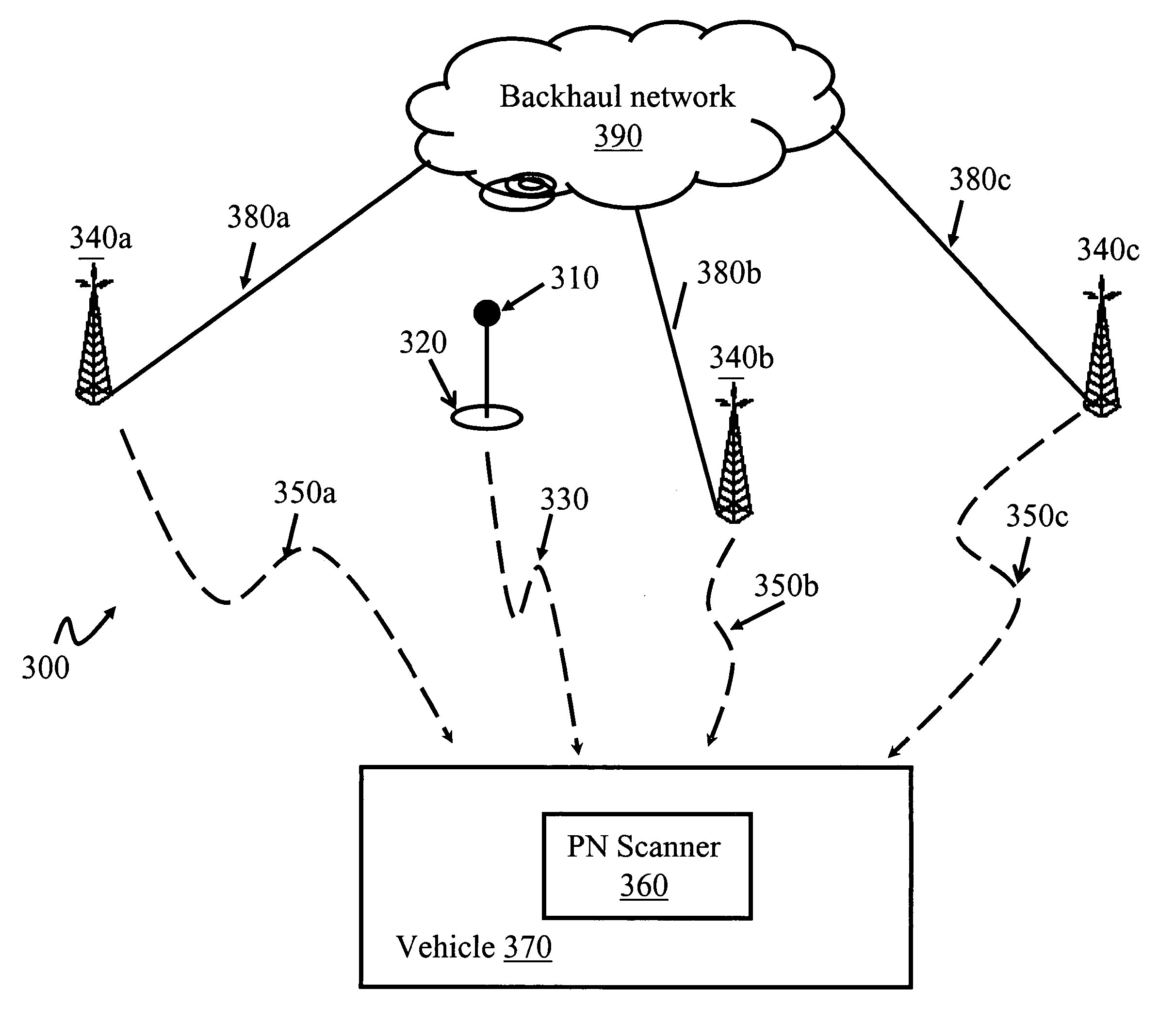
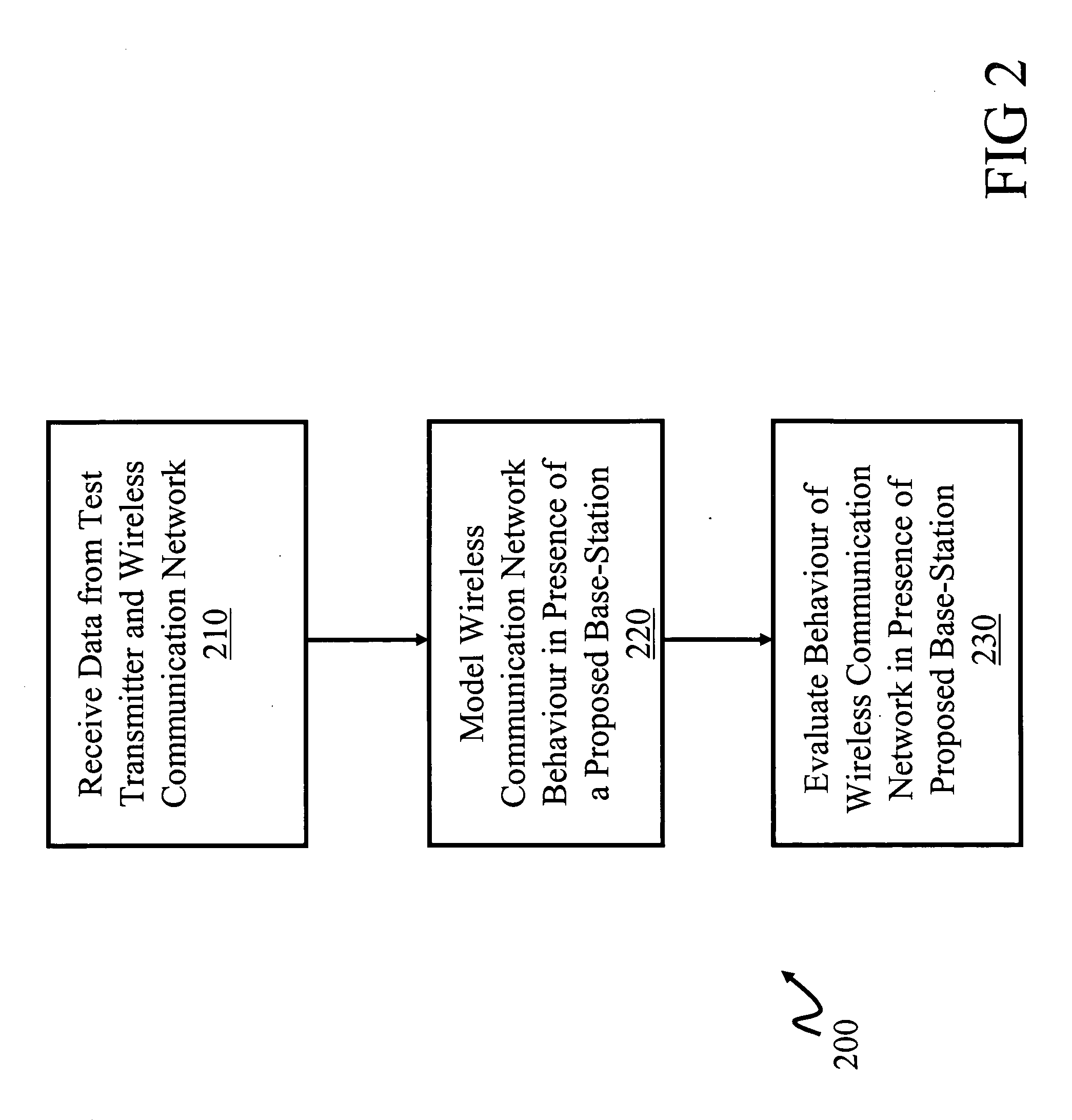
[0021] A fourth broad aspect of the present invention seeks to provide a method for analysing a wireless network with a proposed base station added at a proposed location. The first step of the method is receiving first data comprising a signal strength for a test signal received at a measurement location from a test transmitter at the proposed location. The second step of the method is receiving second data comprising a power spectrum density indication for the existing wireless network at the measurement location and signal strengths for a plurality of communication signals received at the measurement location, each communication signal corresponding to a respective one of a plurality of communication channels transmitted by one or more existing base stations within the wireless network. The third step of the method is estimating a signal strength for a signal received at the measurement location from the proposed base station using the signal strength for the test signal. The fourth step of the method is estimating a power spectrum density at the measurement location for the wireless network with the proposed base station added using the power spectrum density indication for the existing wireless network at the measurement location and the estimate of the signal strength for a signal received at the measurement location from the proposed base station. The fifth step of the method is estimating a signal-to-noise ratio for a communication channel at the measurement location transmitted by the proposed base station by dividing the estimate of the signal strength for a signal received at the measurement location from the proposed base station by the estimate of the power spectrum density at the measurement location for the wireless network with the proposed base station added. The sixth step of the method is estimating a signal-to-noise ratio for each of the plurality of communication channels at the measurement location, each signal-to-noise ratio comprising the signal strength for the respective communication signal received at the measurement location from the corresponding existing base station divided by the estimate of the power spectrum density at the measurement location for the wireless network with the proposed base station added.

Problems solved by technology

Consequently, planning of such networks has become more challenging as each base station, which receives and transmits cell-phone data, can process only a limited amount of such data on a particular range of frequencies or range of channels.
However this has the disadvantage of having to deploy the radios and associated equipment uniformly across the network, with each existing base station being outfitted with the new equipment to maintain consistent quality of service.
The associated cost of this deployment is very high, and additionally over-utilizes precious spectrum resources.
Non-uniform addition of radios leads to conditions where a cell-phone moving within the coverage area may have to switch networks as it moves from an area equipped with new radios to an area lacking new radios, a process known as a hard hand-off.
Hard hand-offs are not reliable, leading to an increased number of dropped calls and thus degraded quality of service.
However it is important to carefully plan the location of these new sites as the cost of erecting a base station is high, including the equipment and cost of a long-term lease of a site.
Introducing a new base station can be problematic in areas where several base station signals are detectable by a cell-phone located in these areas.
The disadvantage of having more than three strong base station signals in an area is that interference between possible hand-off states will occur, again leading to an increased numbers of dropped calls and degraded quality of service.
Current network planning methods do not adequately address this situation.
Hence, evaluating the location and characteristics of a proposed base station can be a challenging process as it is important to ensure both acceptable coverage of an area as well as limiting the number of possible hand-off states, a balance between too few available signals and too many.
If the base station, when built, improves network coverage in one area, but results in a detrimental number of hand-off states in areas which overlap with adjacent base stations, the result can be decreased quality of service or suboptimal capacity in these overlap areas and a need to either move the base station or build additional base stations to solve the problem, both unfavourably expensive options.
However a disadvantage of these methods is that the simulations are often inaccurate as the land-cover models they are based on assume unrealistic uniformity of buildings and foliage.
Another disadvantage to these methods is that they cannot directly take into account the effect of the new base station on the existing network except through the limited simulation models described above.
Though some empirical techniques exist to improve the land-cover model, the simulation still has no accurate picture of existing network coverage.

Method used


Image

  • System and method for coverage analysis in a wireless network
  • System and method for coverage analysis in a wireless network
  • System and method for coverage analysis in a wireless network

Examples


Embodiment Construction

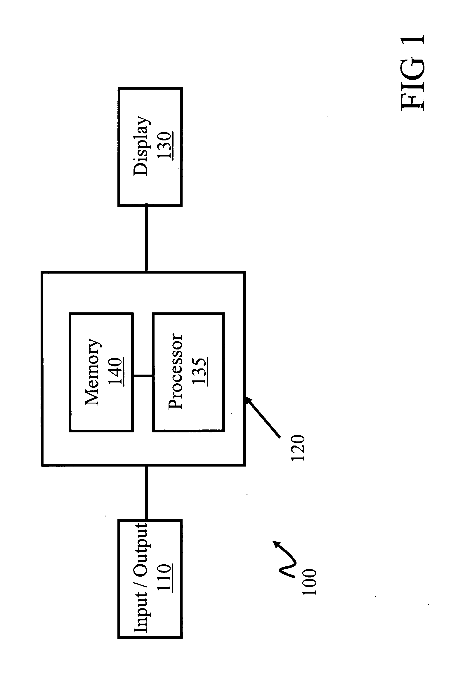
[0034]FIG. 1 depicts a system 100 operable to conduct coverage analysis in a network according to embodiments of the present invention. The system 100 comprises an input / output apparatus 110, a computing apparatus 120, and display apparatus 130. The computing apparatus is operable to analyze data and comprises a processor apparatus 135 and a memory apparatus 140. The system 100 is configured to receive network and test transmitter data through the I / O apparatus 110, process the network and test transmitter data with the processor apparatus 135, store the results of the processed data on the memory apparatus 140, and display results of the processed data on the display apparatus 130. In one embodiment the system 100 is a computer, such as a personal computer, that is typically comprised of hardware suitable for processing data and includes a central processing unit, a random access memory, hard-disk storage, a network interface for communicating over a network, and removable media st...


PUM


Abstract

The present invention is a system and method for coverage analysis in a wireless network. The invention seeks to evaluate the location and characteristics of a proposed base station in a wireless communication network, prior to the base station being erected. Data is collected from both: a test transmitter of known characteristics, erected at the proposed location for the proposed base station; and from a plurality of wireless channels of the existing network. The data may be collected at a plurality of measurement locations. The collected data is used to model and subsequently evaluate the behaviour of the network in the presence of channels that would be introduced into the network if the new base station were erected. Modeled data may include estimates of signal to noise ratios for various wireless channels for both existing base stations and the proposed base station, at the measurement location. The model data may be displayed on a GUI, depicting modeled signal characteristics in a geographical area surrounding the proposed base station, to estimate overall acceptability of a proposed base station at a proposed location before incurring the cost of installing the base station.

Description

FIELD OF THE INVENTION [0001] The present invention is directed to wireless communications networks and, in particular to a system and method for coverage analysis in a wireless network. BACKGROUND OF THE INVENTION [0002] The use of cell phones has become ubiquitous in today's society, with the use of such devices growing exponentially worldwide with each passing year. Consequently, planning of such networks has become more challenging as each base station, which receives and transmits cell-phone data, can process only a limited amount of such data on a particular range of frequencies or range of channels. [0003] Several methods currently exist to address this increasing volume of data. A first method is to add a new network to the existing network by adding new radios to existing base stations, the new network operating at a different range of frequencies from the existing network. However this has the disadvantage of having to deploy the radios and associated equipment uniformly a...

Claims


Application Information

Patent Timeline
Patent Type & Authority Applications(United States)
IPC IPC(8): H04B17/00H04Q7/20H04W16/18
CPCH04W16/18
Inventor GAZZOLA, JAMES PETER
Owner BCE
Learn More