
Electromagnetic testing model of human hand

a technology of electromagnetic testing and human hand, applied in the field of electromagnetic testing equipment, can solve the problems of loss of signal energy, complicated matters, and dramatic change in the performance of the antenna

Active Publication Date: 2006-06-15
GOOGLE TECH HLDG LLC
View PDF7 Cites 20 Cited by
  • Summary
  • Abstract
  • Description
  • Claims
  • Application Information

AI Technical Summary

Problems solved by technology

Although considered in isolation, an antenna of a wireless communication device can be analyzed and understood using a variety of mathematical methods, placing the antenna near a person's body complicates matters and can dramatically change the performance of the antenna from what is predicated based on mathematical models of the antenna in isolation.
Interaction with a person's body may lead to loss of signal energy, and alteration of the gain pattern.
However, such human hand models suffer from the deficiency that the position of the fingers is substantially fixed so that they can not be manipulated to grip devices of different shapes and sizes in different ways.
Also, once constructed, the electromagnetic properties of such model hands are fixed, so that they are matched to a human hand at one particular frequency, and unsuitable for testing at other frequencies or for evaluating a range of human hand electrical characteristics.

Method used


Image

  • Electromagnetic testing model of human hand
  • Electromagnetic testing model of human hand
  • Electromagnetic testing model of human hand

Examples


Embodiment Construction

[0019] As required, detailed embodiments of the present invention are disclosed herein; however, it is to be understood that the disclosed embodiments are merely exemplary of the invention, which can be embodied in various forms. Therefore, specific structural and functional details disclosed herein are not to be interpreted as limiting, but merely as a basis for the claims and as a representative basis for teaching one skilled in the art to variously employ the present invention in virtually any appropriately detailed structure. Further, the terms and phrases used herein are not intended to be limiting; but rather, to provide an understandable description of the invention.

[0020] The terms a or an, as used herein, are defined as one or more than one. The term plurality, as used herein, is defined as two or more than two. The term another, as used herein, is defined as at least a second or more. The terms including and / or having, as used herein, are defined as comprising (i.e., open...


PUM


Abstract

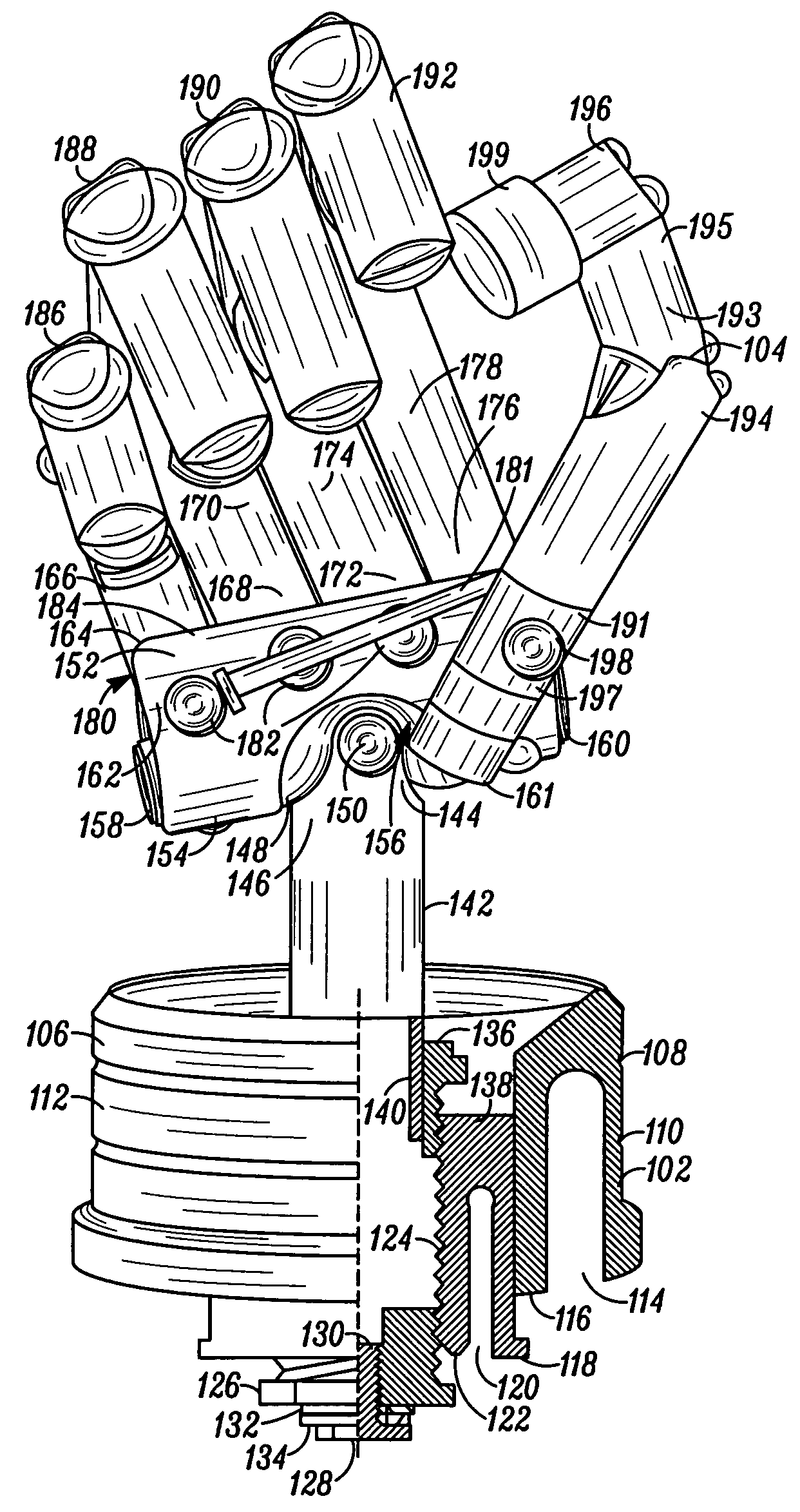
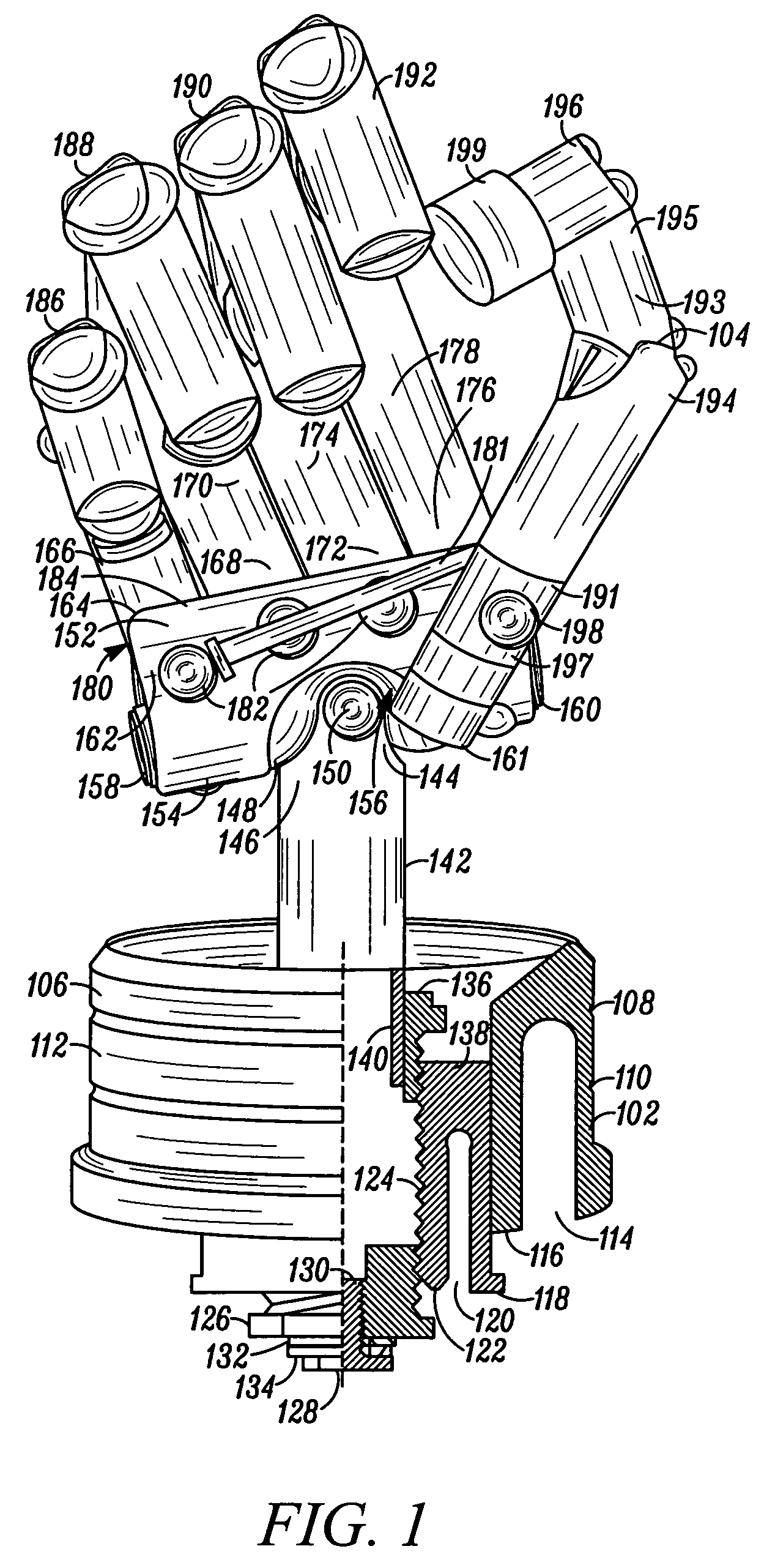
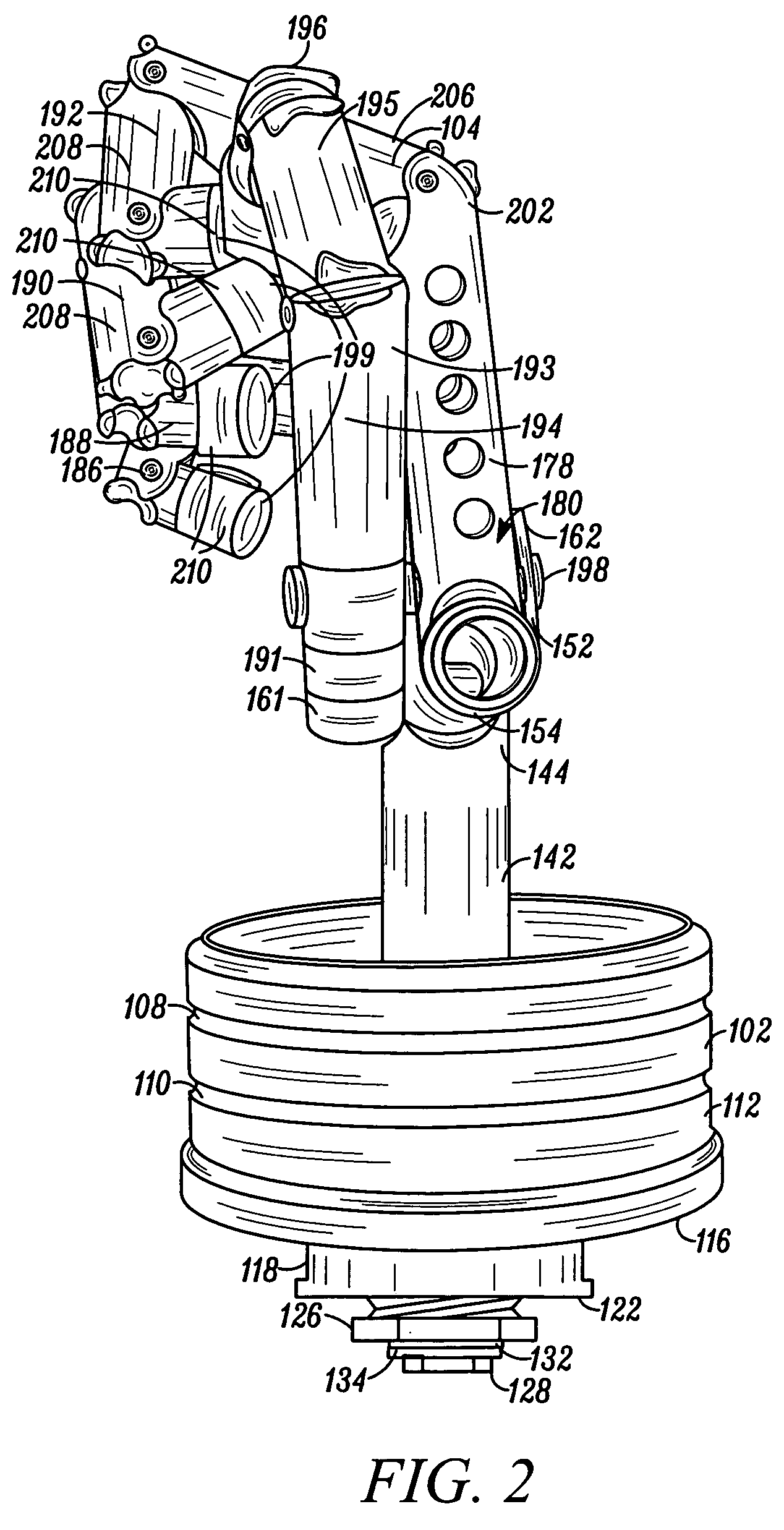
Model human hands (902) for use in electromagnetic (e.g., microwave and RF) testing comprise a skeleton (1200, 104) of dielectric tubes (142, 148, 166, 170, 174, 178, 206, 208, 210, 1202, 1212, 1214, 1216, 1228, 1230, 1236, 1240, 1242, 194, 195, 196) inside a glove (908) that is filled with a fluid that has electrical properties that match that of a typical human hand at a particular frequency. According to certain embodiments the model hands comprise thumbs (193, 1236) that are located out of a plane of palms of the model hands. According to one embodiment the dielectric tubes are pivotally coupled to each other and biasing means (181,702) are provided to bias the hand into a gripping position so that the model human hand is able to grip different types of wireless communication devices (802) in different ways.

Description

FIELD OF THE INVENTION [0001] The present invention relates in general to microwave test equipment. More particularly, the present invention relates to models used in evaluating the effect of the human body on signals directed to and from wireless communication devices. BACKGROUND OF THE INVENTION [0002] The past decade has witnessed widespread adoption of personal wireless communication devices, including handheld cellular telephones, dedicated text messaging devices, and hybrid devices that combine communication and other functions. Wireless communication devices include antennas that are used to transmit and receive information-bearing RF and / or microwave signals. Antennas can be characterized by the efficiency with which they radiate and receive signals and by their gain patterns, which characterize how well the antenna can transmit and receive signals in each direction. [0003] Handheld wireless communication devices differ from larger radio communication equipment in that they ...

Claims


Application Information

Patent Timeline
IPC IPC(8): H04B17/00
CPCG09B23/32
Inventor MOLLER, PAUL J.RUBINSTEIN, BORIS M.
Owner GOOGLE TECH HLDG LLC
Learn More