
Wireless communication system

a communication system and wireless communication technology, applied in wireless communication, multi-channel communication, signalling characterisation, etc., can solve the problems of increasing the error rate of received control information, reducing the remaining resource, and reducing the throughpu

Active Publication Date: 2006-06-15
FUJITSU CONNECTED TECH LTD
View PDF31 Cites 79 Cited by
  • Summary
  • Abstract
  • Description
  • Claims
  • Application Information

AI Technical Summary

Benefits of technology

[0031] Accordingly, it is a general object of the present invention to provide a novel and useful wireless communication in which one or more of the problems described above are eliminated.

Problems solved by technology

If the resource (time, frequency, and spreading code, for example) is allocated in advance in accordance with the estimated maximum amount of control information, when the MIMO multiplexing N increases, remaining resource is reduced, which may result in decrease in throughput.
On the other hand, if MIMO multiplexing is used for increasing the number of bits transmitted as the control information, even a user in a wireless transmission environment where MIMO multiplexing is not suitable is required to receive control information containing many bits, which may increase error rate of received control information.
If the power of control channel is increased in order to improve transmission quality, interference with other channels may consequently increase, which results in reduction in the throughput of a wireless communication system.
In addition, not all mobile terminals in a mobile phone system usually support MIMO function.
There are mobile terminals supporting MIMO function and mobile terminals not supporting MIMO function in such a mobile phone system, which means that the control channel can not always be transmitted using MIMO system.
However, if it is desired to increase the information amount of control channel by changing the rate of error correction encoding without using MIMO, the control of the traffic channel and the control channel becomes very difficult because the transmission rate of MIMO multiplexed traffic channel is increased.

Method used


Image

  • Wireless communication system
  • Wireless communication system
  • Wireless communication system

Examples


Embodiment Construction

[0052] The preferred embodiment of the present invention are described below with reference to the drawings.

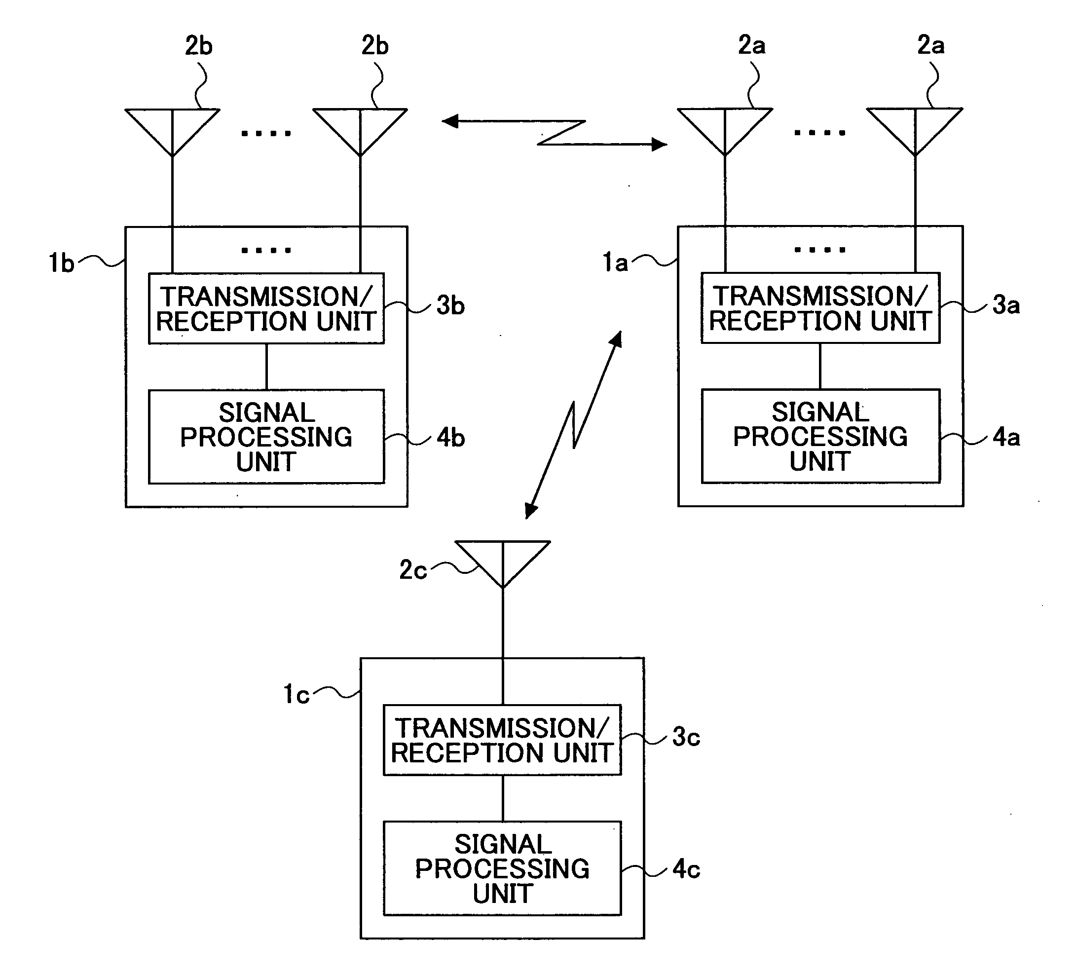
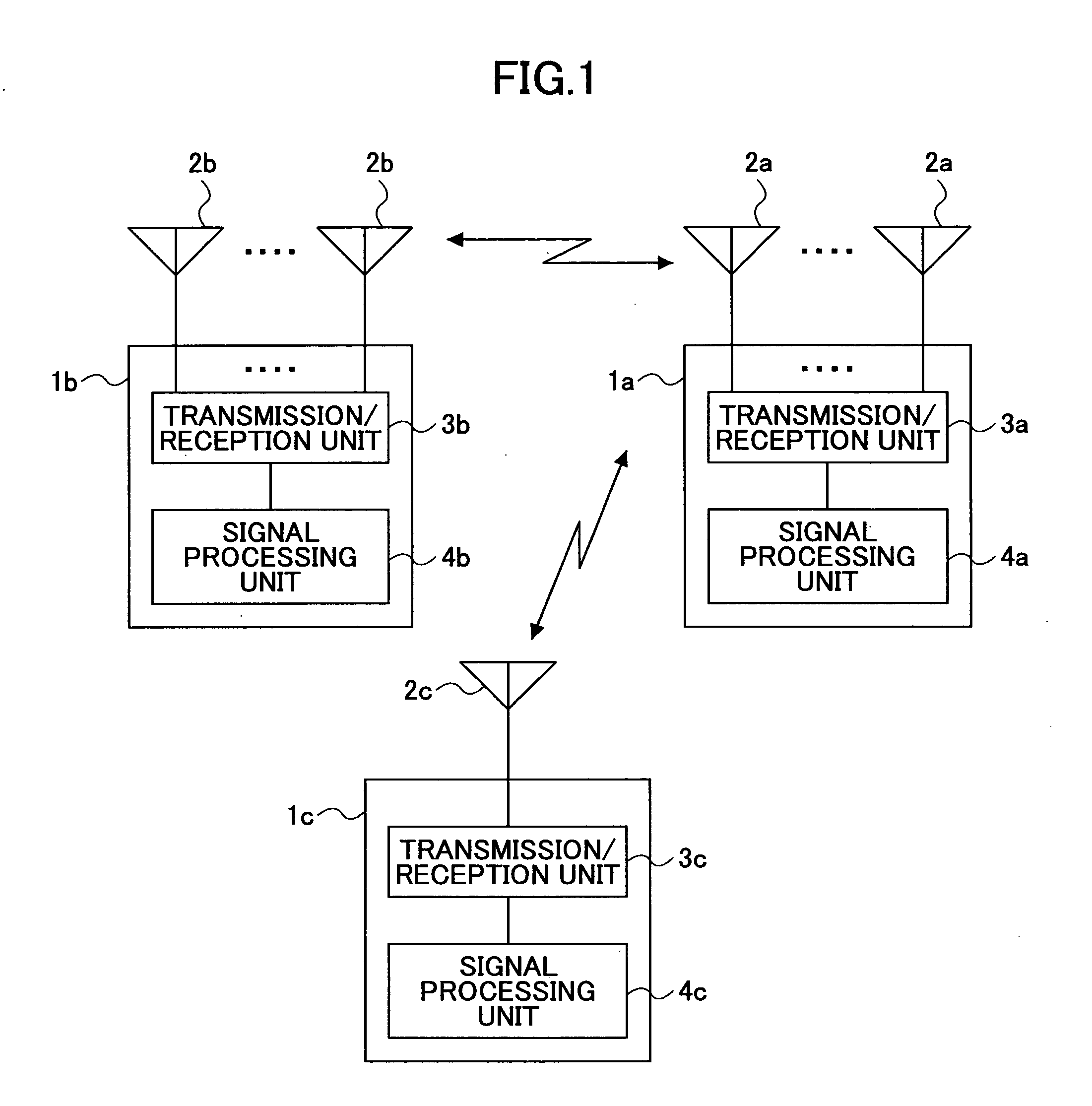
[0053] Referring to FIG. 1, a wireless communication system according to the present invention includes MIMO wireless communication apparatuses 1a, 1b that can communicate through a plurality of antennas 2a, 2b and a non-MIMO wireless communication apparatus 1c that can communicate through a single antenna or a plurality of antennas 2c. The MIMO wireless communication apparatus 1a, 1b includes a communication unit (transmission / reception unit 3a, 3b and signal processing unit 4a, 4b) configured to transmit and receive control information divided into a second control information containing information related to the demodulation and decoding of traffic channel and a first control information containing information related to the MIMO separation of the second control information.

[0054] In other words, the wireless communication apparatus 1a includes a transmission processing ...


PUM


Abstract

A wireless communication system is disclosed including a MIMO wireless communication apparatus that can communicate through multiple antennas and a non-MIMO wireless communication apparatus that can communicate through a single antenna or multiple antennas. The MIMO wireless communication apparatus includes a communication unit configured to transmit and receive control information divided into a second control information containing information related to the demodulation and decoding of traffic channel and a first control information containing information related to the MIMO separation of the second control information.

Description

BACKGROUND OF THE INVENTION [0001] 1. Field of the Invention [0002] The present invention generally relates to a wireless communication system and a wireless communication apparatus included therein that communicates data, and more particularly, to a wireless communication system and a wireless communication apparatus included therein having one or more antenna. [0003] 2. Description of the Related Art [0004] A conventional wireless communication apparatus generally has an antenna for transmission and an antenna for reception, or a single antenna for transmission and reception. A wireless communication apparatus having multiple antennas using space-diversity reception techniques is known. A wireless communication system is also known as a Multiple Input Multiple Output (MIMO) system in which both a transmitting apparatus and a receiving apparatus are provided with multiple antennas, and the transmitting apparatus and the receiving apparatus communicate using space division multiplex...

Claims


Application Information

Patent Timeline
Patent Type & Authority Applications(United States)
IPC IPC(8): H04B7/00H04M1/00H04J99/00H04W16/28H04W28/06
CPCH04B7/0613H04B7/0697H04L1/1812H04L1/0025H04L1/0026H04L1/0003H04W72/23H04B7/0413H04L5/003H04L27/34
Inventor DATEKI, TAKASHIYANO, TETSUYA
Owner FUJITSU CONNECTED TECH LTD
Learn More