
Motor vehicle seat

Inactive Publication Date: 2006-06-15
DAIMLER AG
View PDF10 Cites 2 Cited by
  • Summary
  • Abstract
  • Description
  • Claims
  • Application Information

AI Technical Summary

Benefits of technology

[0013] The swivel axis of the impact plate on the head support can be so positioned that, in the event of an accident, the head of the vehicle passenger always comes to rest as close as possible to the swivel axis. As a result, the forces acting on the impact plate in the vicinity of the swivel axis are passed to the impact plate, whereupon small lever arms emerge. Because of the small lever arms, backward movement of the head is limited when the impact plate is displaced to the rear because of the redirected forces. As a result, the head is held in a position lying as far forward as possible, and an unnecessary backward displacement of the head is prevented. The effect of the invention is also thereby reinforced by preventing movement of the head to the rear, especially in relation to the upper body of the vehicle passenger.
[0014] In contrast to the technology discussed at the outset, the invention has the advantage of omitting a procedure for head support or parts of it in the event of an impact. As a result, the vehicle seat of the invention is, basically, simpler to manufacture and install. That entails significant cost advantages. In addition, no expensive control is necessary in the arrangement of the invention, which, in addition to the cost advantage, represents an advantage with regard to the reliability of the system; in order to be effective, the construction of the invention does not have to move. It is constantly effective. Thus, by means of the invention, there is a constantly ready and very reliable system available. In addition, it is also important that a non-moving system is much more simple to design with regard to its fatigue strength. During its lifetime, the head support is subject to other demands; for example, the head support frequently serves as a handle for persons sitting in the rear to pull themselves up when exiting.
[0015] The connecting element to secure the head support to the seat back support can be constructed as a curve. For example, two rod-shaped connection elements can be provided which are aligned parallel to each other and which extend between the seat back support and the head support. In order to avoid any displacement of the head support relative to the seat back in the event of an accident, the connection elements can be produced from a high strength material, for example steel. In this way the connection elements can be prevented from deforming when, in the event of an accident, the head comes in contact with the head support after its movement to the rear. Naturally other materials are conceivable, like plastics and other metals.
[0016] The connection can be so designed that it permits a translational movement of the connection elements relative to the seat back support. It is also is so aligned, relative to the support, that, in the event of an accident, it is capable of supporting the head of a vehicle passenger in a position which is positioned forward relative to the upper body of the vehicle passenger. As a result, in an impact, a movement of the vehicle passenger to the rear can be arrested, and the head, in the end phase of the movement, does not move further backward relative to the upper body. Instead, the movement of the head is stopped at about the same time as the movement of the upper body. In other words, the arrangement of the invention ensures that the backward movement of a vehicle passenger in an accident is braked so that there is no relative movement between the head and the upper body. As a result, cervical vertebrae injuries can be avoided.
[0017] The curvature of the connection elements as well as their alignment relative to the seat back can be selected so that, independent of the position of the seat back, which for comfort reasons can be adjusted in its height as well as its inclination, as well as the head support, which also can be adjusted in height for comfort reasons, the head support is also so aligned relative to the seat back support that, in the event of an accident, a support of the head is assumed in a forward displaced position relative to the upper body. In order to guarantee that, the movement paths of the seat back and head support, the radius of the connection elements, and the alignment of the connection elements to the seat back must be exactly matched to each other.
[0018] The seat back support can manifest a transverse traverse which basically consists of a U-shaped profile. The transverse traverse extends horizontally in the seat back and is placed on its upper end. It can serve, for example, to accept the connection elements.

Problems solved by technology

That results in the danger of cervical vertebrae injuries, especially in an end phase in which the upper body of the passenger again rests on the seat, while the head moves still further backward relative to the upper body.
A disadvantage of these known active head supports is that they have relatively expensive constructions.
Such an expensive construction causes high costs in manufacture as well as in assembly.
Both the activation elements as well as the control system increase the complexity and thus the costs of such a system significantly.
According to another embodiment, the swivel movement can be so limited that swinging is only possible within certain limits.
Because of the small lever arms, backward movement of the head is limited when the impact plate is displaced to the rear because of the redirected forces.
Second, in the event of an accident, the padding permits an immersion of the upper body of the passenger into the seat back.

Method used


Image

  • Motor vehicle seat
  • Motor vehicle seat
  • Motor vehicle seat

Examples


Embodiment Construction

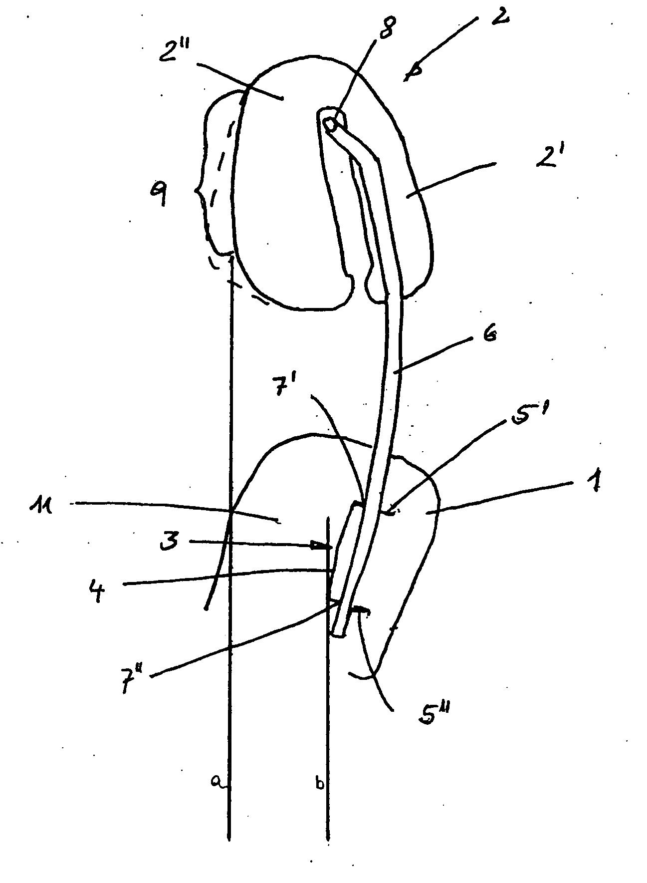
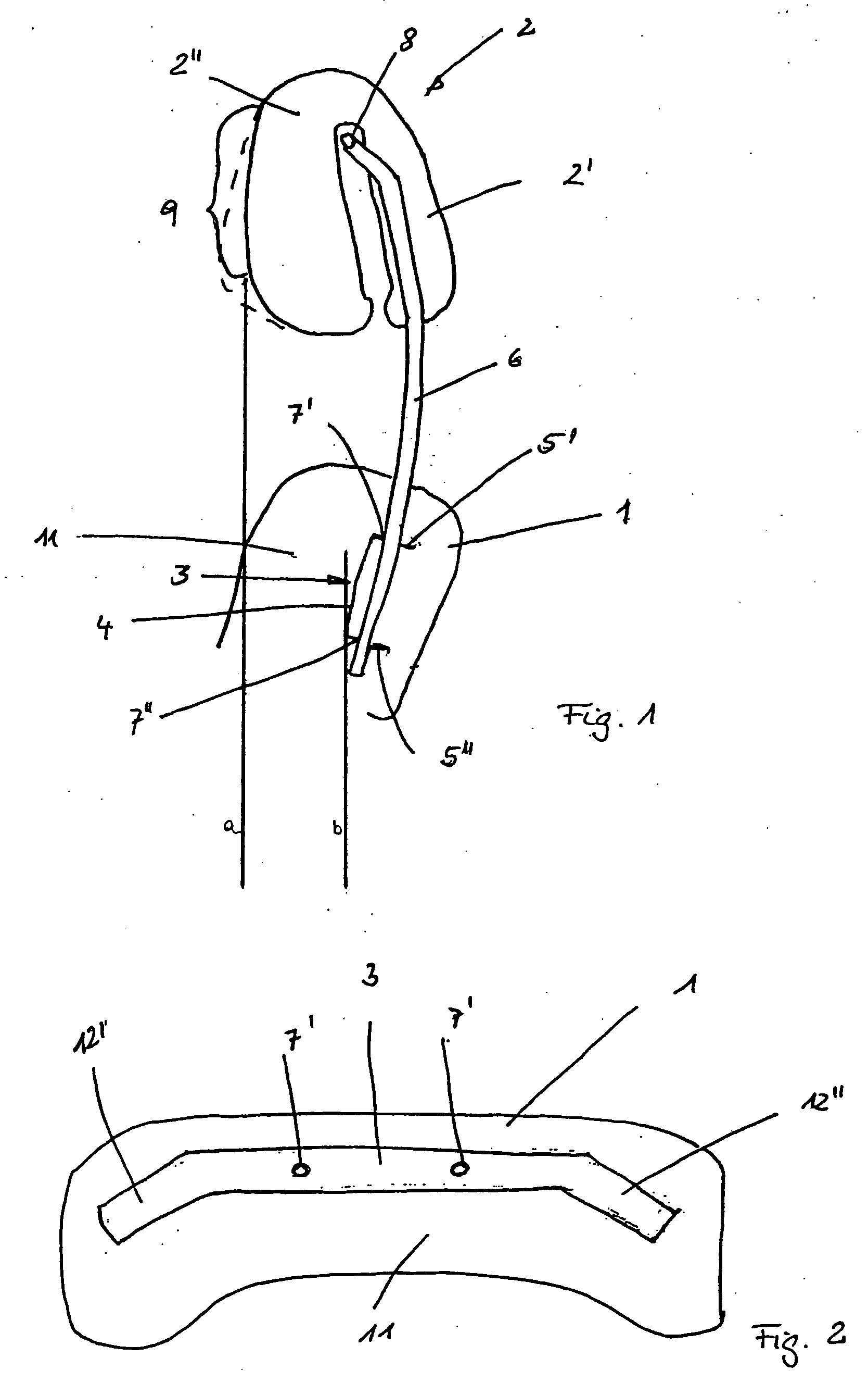
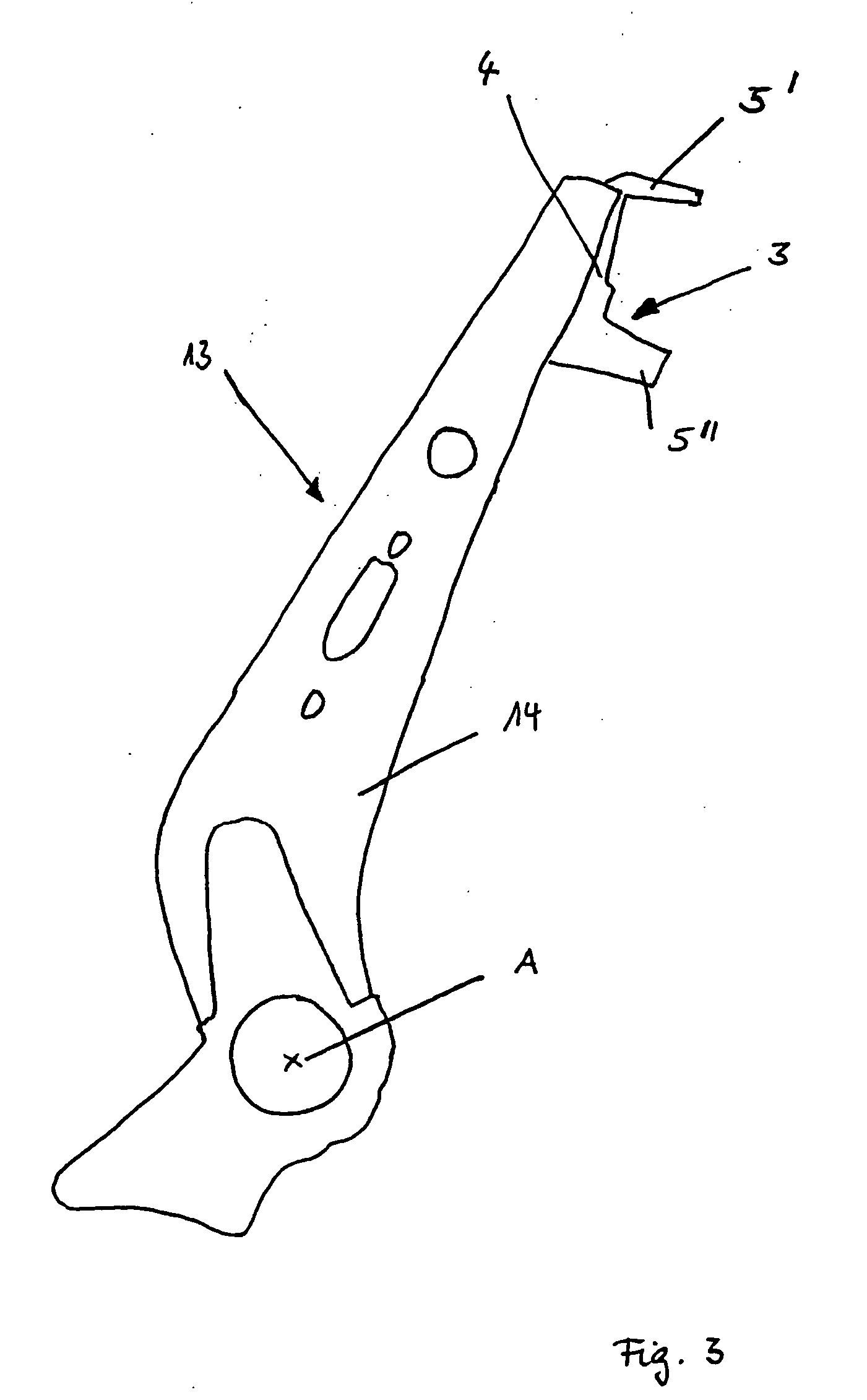
[0028] In FIG. 1 a vertical longitudinal cut through a seat back 1 of a motor vehicle seat of the invention with a head support 2 is depicted. The seat back 1 manifests a seat back support from which U-shaped a transverse traverse is shown in FIG. 1. The transverse traverse 3 consists of a U-shaped profile which manifests a base 4 as well as two side flanks 5′ and 5″. The base 4 is longer than the two side flanks 5′ and 5″. The U-shaped transverse traverse 3 is aligned in the seat back so that it has the base 4 facing in the direction of a vehicle passenger sitting on the seat. Its opened side thus points to an area lying behind the vehicle seat.

[0029] The head support 2 is connected to the seat back 1 by means of a long connection element 6. The connection element 6 is constructed in a rod-shape. The downward-pointing end of the connection element 6 is connected to the transverse traverse 3 of the seat back support. For that reason holes 7 and 7″ are provided in the side flanks 5′...


PUM


Abstract

A motor vehicle seat with a seat back has a seat back support and a head support attached to the seat back support by a connection element. The motor vehicle seat increases vehicle passenger safety despite its simple construction by connecting the head support to the seat back support. In addition, the head support is positioned relative to the seat back support so that, in the event of an accident, a support of the head of the vehicle passenger occurs in a forward deployed position in relation to the upper body, so that a relative movement between the head and the upper body is prevented.

Description

BACKGROUND AND SUMMARY OF THE INVENTION [0001] The invention involves a motor vehicle seat. [0002] In the event of an abrupt vehicle deceleration, like with a frontal impact or a rear impact of a vehicle against an obstacle, the vehicle decelerates, at first, more quickly than a passenger located inside the vehicle, so that there is a relative movement between the passenger and the vehicle. In a frontal impact, the passenger moves forward in the vehicle. This forward movement of the passenger inside the vehicle follows, as a rule, a movement aimed to the rear. In an impact from the rear, there is an immediate movement to the rear. That results in the danger of cervical vertebrae injuries, especially in an end phase in which the upper body of the passenger again rests on the seat, while the head moves still further backward relative to the upper body. [0003] A variety of so-called “active head supports” are known by means of which the danger of cervical vertebrae injuries is minimize...

Claims


Application Information

Patent Timeline
IPC IPC(8): B60N2/42B60N2/48
CPCB60N2/4838B60N2/4864B60N2/4885B60N2/838B60N2/888B60N2/865
Inventor ORIZARIS, VASILIOS
Owner DAIMLER AG
Learn More